Power amplifier

a power amplifier and amplifier technology, applied in the direction of rf amplifiers, amplifiers with semiconductor devices/discharge tubes, high frequency amplifiers, etc., can solve the problems of poor efficiency of conventional power amplifiers, signal distortion, gain compression, etc., to improve efficiencies and linearity of power amplifiers.

Inactive Publication Date: 2015-12-17
SHENZHEN SOUTH SILICON VALLEY MICROELECTRONICS
View PDF3 Cites 1 Cited by
  • Summary
  • Abstract
  • Description
  • Claims
  • Application Information

AI Technical Summary

Benefits of technology

[0011]In summary, according to the power amplifier provided by the present invention, the power amplifier units of the power amplifier may be enable to operate in different class region, such as class-A, class-B or class-AB etc., in according with the bias voltage supplied by the bias unit. Comparing with the conventional power amplifier limited to operate in only one class region, the power amplifier provided by the present invention is not limited to operate in one class region, since the operat...

Problems solved by technology

A conventional linear power amplifier, such as a class-A, a class-B or a class-AB power amplifier, biases an active device (the power amplifier) thereof by a fixed DC current , so as to obtain better linearity even though efficiency of the...

Method used


Image

  • Power amplifier
  • Power amplifier
  • Power amplifier

Examples


Embodiment Construction

[0018]Reference will now be made in detail to the present preferred embodiments of the invention, examples of which are illustrated in the accompanying drawings. Wherever possible, the same reference numbers are used in the drawings and the description to refer to the same or like parts.

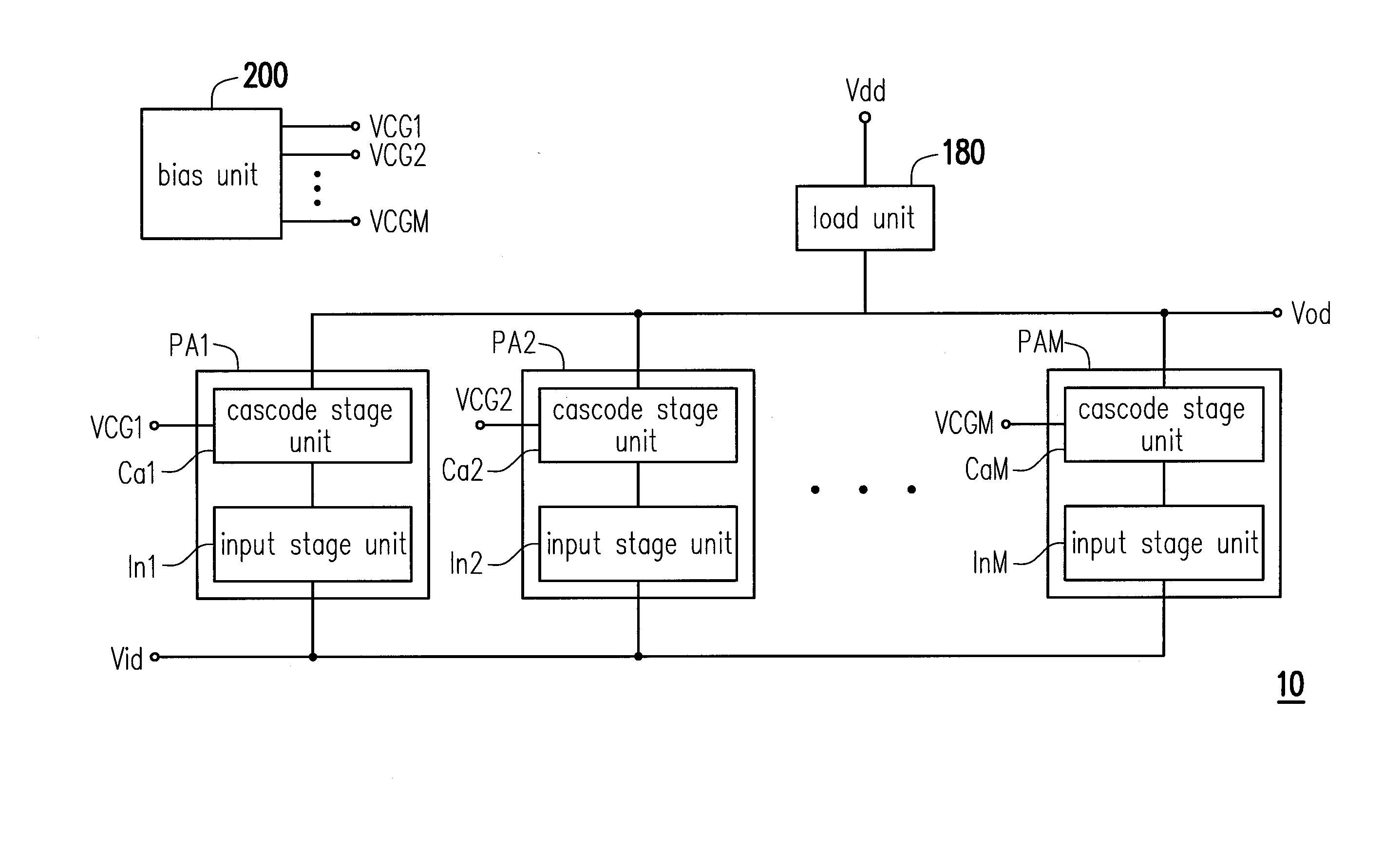
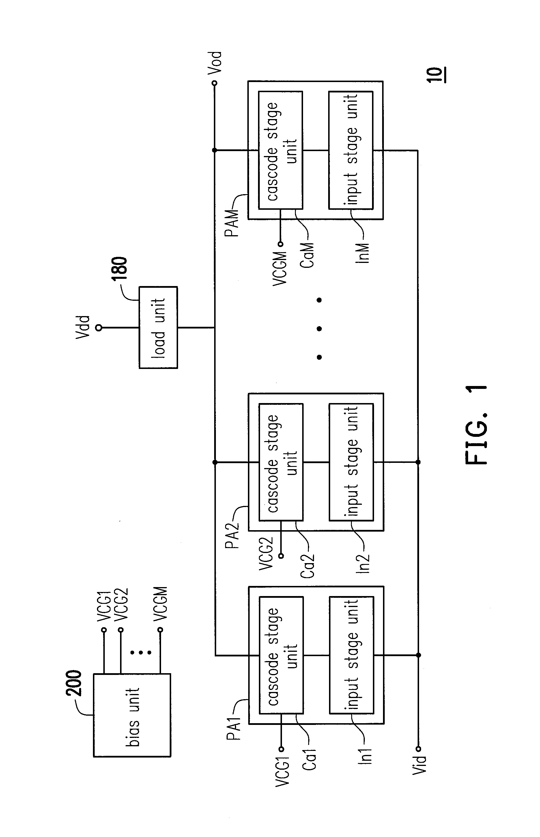
[0019]FIG. 1 is a schematic diagram of a power amplifier according to an embodiment of the invention. Referring to FIG. 1, the power amplifier 10 comprises M power amplifier units PA1, PA2, . . . , PAM and a bias unit 200, wherein M is a integer greater than 1. The power amplifier units PA1, PA2, . . . , PAM are connected in parallel with each other to receive a differential input signal Vid. The power amplifier units PA1, PA2, . . . , PAM perform a power amplifying so as to output a differential output signal Vod. Besides, a load unit 180 is coupled between each of the power amplifier units PA1, PA2, . . . , PAM and a reference voltage Vdd.

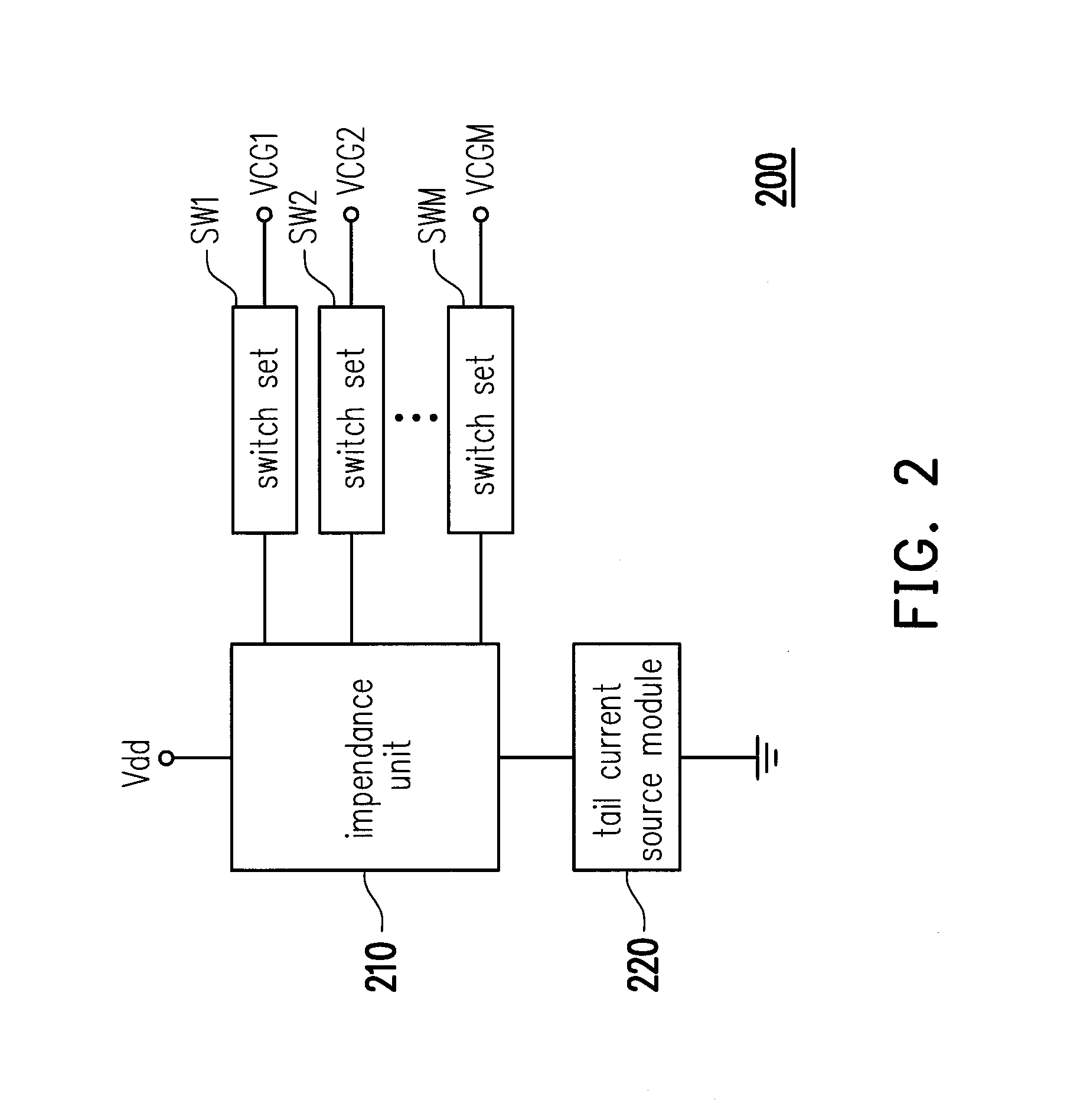
[0020]The bias unit 200 is coupled to each of the power ampl...


PUM


Abstract

A power amplifier is provided. The power amplifier comprises a plurality of power amplifier units and a bias unit. The power amplifier units are connected in parallel with each other to receive a differential input signal. The power amplifier units perform a power amplifying so as to output a differential output signal. The bias unit is coupled to the power amplifier units and supplies a plurality of bias signals to the power amplifier units respectively. At least two of the power amplifier units are enable to operate in different class regions in according with the corresponding bias signals.

Description

BACKGROUND OF THE INVENTION[0001]1. Field of the Invention[0002]The present invention relates to a power amplifier. More particularly, the present invention relates to a power amplifier comprising a plurality of power amplifier units operating in different class regions.[0003]2. Description of Related Art[0004]Wireless communication is without a doubt a popular research and commercial topic. Typically, wireless communication starts from a transmitter processing input signals to output signals that then transmit “wirelessly” to a receiver. Power amplifier (PA) is an important device in a radio frequency (RF) front-end circuit for a transmitter. Specifically, a power amplifier is used to amplify the broadcast signals at the transmission (TX) terminal of a radio frequency circuit. With the popularity of portable communication systems, maximum output power and output power efficiency has become the critical factors for the development of wireless transmission.[0005]A conventional linear...

Claims


Application Information

Patent Timeline
IPC IPC(8): H03F3/21H03F3/45H03F3/19
CPCH03F3/211H03F3/19H03F2203/21127H03F2203/45116H03F2200/451H03F3/45076H03F1/223H03F3/193H03F2203/45352H03F3/45188
Inventor LIAO, HUA-YUWANG, CHENG-YUCHANG, YING-TANG
Owner SHENZHEN SOUTH SILICON VALLEY MICROELECTRONICS
Why Eureka
Try Eureka