
Object information acquiring apparatus and laser apparatus used therein

Inactive Publication Date: 2015-12-24
CANON KK
View PDF6 Cites 2 Cited by
  • Summary
  • Abstract
  • Description
  • Claims
  • Application Information

AI Technical Summary

Benefits of technology

The patent is about an apparatus that can acquire object information by detecting and reducing prelasing, which is an abnormal emission that occurs in a laser apparatus. This prelasing can cause noise and impair the obtaining of accurate biological information. The invention aims to provide an apparatus that can reduce the effects of prelasing and improve the accuracy of object information acquisition.

Problems solved by technology

However, abnormal emission referred to as prelasing occurs when the properties of an apparatus become unstable in a laser apparatus using Q switching.
Consequently, these signals become noise when analyzing the acoustic wave signals and impair the obtaining of accurate biological information (object information).
In addition, since variation occurs in the width per se of a single giant pulse, desired acoustic wave signals are unable to be obtained.
However, suppressing the occurrence of prelasing by controlling the temperature of the laser apparatus has the effect of, for example, increasing the size of the object information acquiring apparatus or increasing production cost.

Method used


Image

  • Object information acquiring apparatus and laser apparatus used therein
  • Object information acquiring apparatus and laser apparatus used therein
  • Object information acquiring apparatus and laser apparatus used therein

Examples


example 1

Practical Example 1

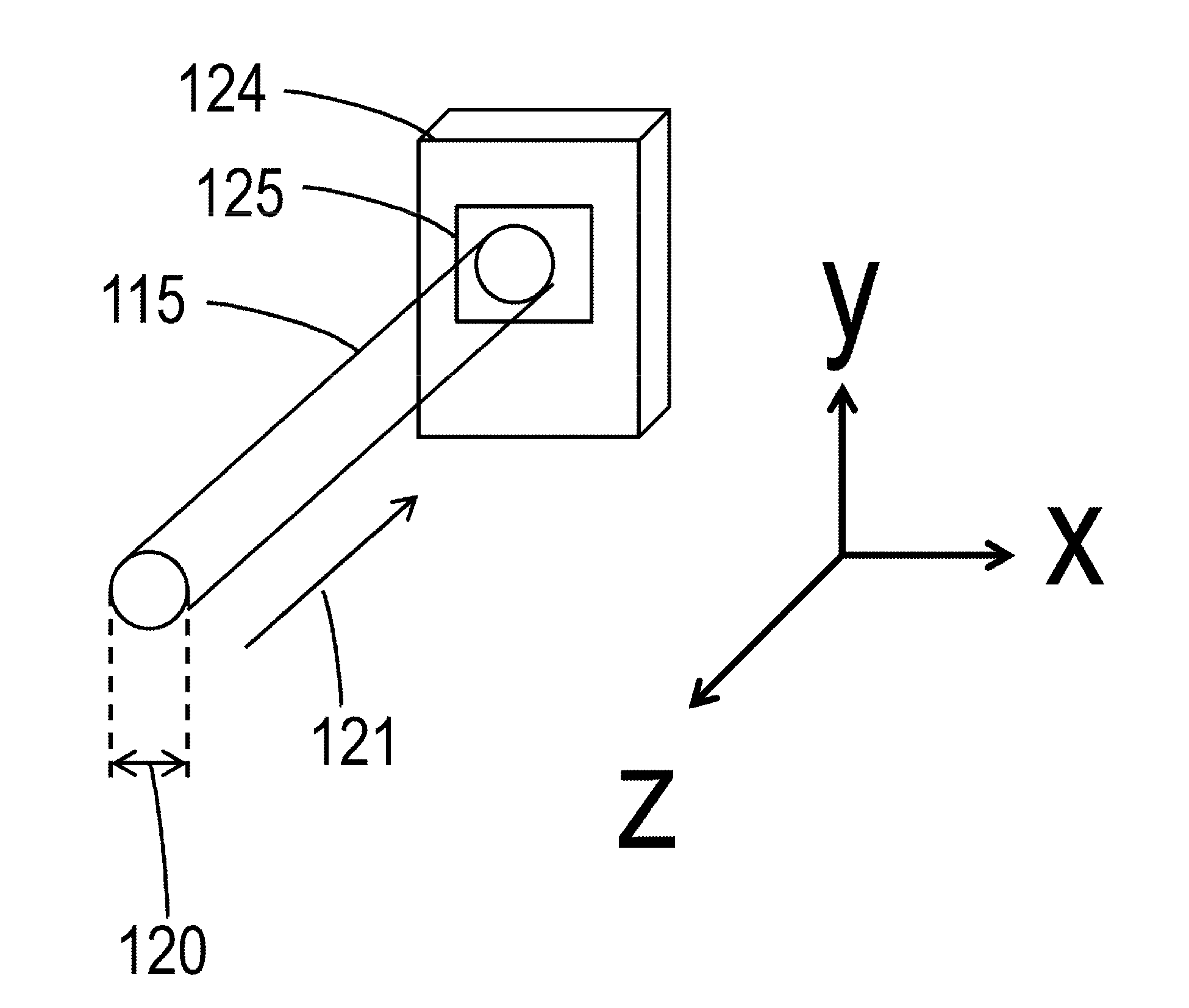
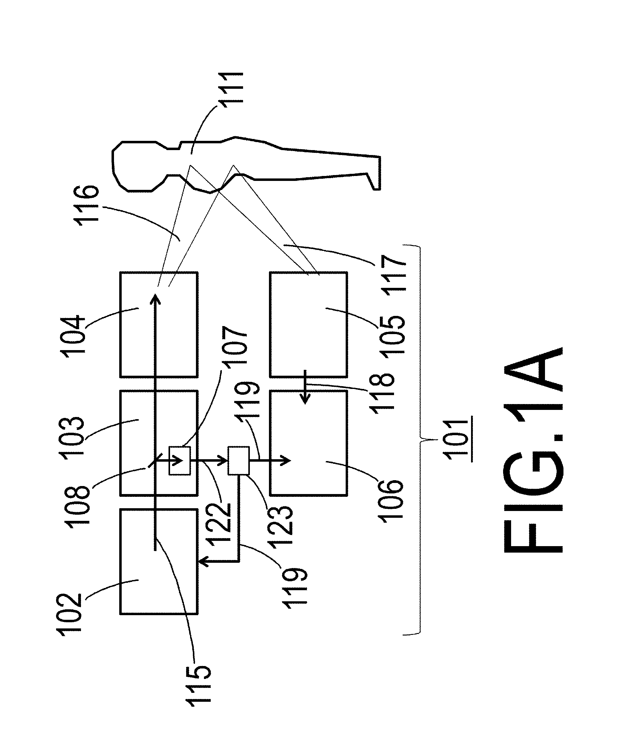
[0026]FIG. 1A is a drawing showing Practical Example 1 of the object information acquiring apparatus of the present invention. An object information acquiring apparatus 101 is provided with a laser light source 102. In addition, the object information acquiring apparatus 101 is further provided with a light-transmitting optical system 103, a irradiator in the form of a light-radiating optical system 104, an acoustic wave receiver 105 and an acoustic wave signal processing unit (an acoustic wave signal processor) 106. In addition, a detector in the form of a laser light sensor 107, a branch mirror 108, an object 111 and radiated light 116 are also shown in FIG. 1A. Moreover, an intensity detection signal 122, an acoustic wave signal 117, an electrical signal 118 and a prelasing determination signal, namely a determination result 119, are also shown in FIG. 1A.

[0027]The object information acquiring apparatus 101 is an apparatus that acquires information on the inter...

example 2

Practical Example 2

[0048]FIG. 5 is a drawing showing a laser light sensor of an object information acquiring apparatus according to Practical Example 2 of the present invention. The same reference numbers are used to indicate those constituents that are the same as those of Practical Example 1, and explanations thereof are omitted unless required. Namely, the laser light sensor of Practical Example 1 was an area sensor that detected the intensity distribution of laser light in the xy plane, namely in two dimensions. However, a one-dimensional line sensor 109b shown in this drawing may also be used for the photo acceptance unit 109b. Namely, the intensity of laser light on this line increases moving from the side near the periphery of the laser width 120 towards the side near the center of the laser width 120. Namely, the intensity distribution of laser light, which includes prelasing and giant pulse oscillation, can be acquired in this manner as well. In particular, the shape of the...

example 3

Practical Example 3

[0049]FIG. 6 is a drawing showing a laser light sensor of an object information acquiring apparatus according to Practical Example 3 of the present invention. The same reference numbers are used to indicate those constituents that are the same as those of Practical Example 1, and explanations thereof are omitted unless required. This laser light sensor 107c only detects laser light over a range that is smaller than the intensity distribution width of the laser light shown in FIGS. 4A and 4B. Namely, the intensity of laser light is detected over a range in which the element addresses of FIGS. 4A and 4B have a diameter of 2 mm. The shape of laser light sensor 109c of the present example differs from the laser light sensor in the form of the photo acceptance unit 109a of Practical Example 1. The element unit 109c of FIG. 6 is positioned in the center of the intensity distribution of the laser light 115 and the element unit 109c is not divided. The range covering a di...


PUM


Abstract

Provided is an object information acquiring apparatus provided with: a laser light source; a detection unit that detects a portion of laser light emitted from the laser light source; a determination unit that determines whether or not abnormal emission is contained in the laser light, based on a detection result of the detection unit; a radiation unit that radiates the laser light onto an object; a reception unit that receives acoustic waves that propagate from the object, based on radiation of the laser light; an acquisition unit that acquires information relating to the object, based on a reception result of the reception unit; and a control unit that controls output of the laser light, based on a determination result of the determination unit.

Description

BACKGROUND OF THE INVENTION[0001]1. Field of the Invention[0002]The present invention relates to an object information acquiring apparatus and a laser apparatus used therein.[0003]2. Description of the Related Art[0004]Photoacoustic tomography systems (photoacoustic measurement systems) are being developed for medical use that use short-pulse oscillation lasers (S. Manohar, et al., “Region-of-interest breast studies using the Twente Photoacoustic Mammoscope (PAM)” Proc. of SPIE, Vol. 6437, 643702). Photoacoustic tomography (PAT) refers to a technique for forming images by irradiating a measurement segment with a pulsed laser for about several tens to several hundred nanoseconds, receiving the photoacoustic waves generated therein with a probe, and processing the resulting received signals. The use of PAT makes it possible to analyze body functions from spectrum measurements based on the absorption coefficients of body tissue.[0005]In addition, lasers using Q switching are used to ge...

Claims


Application Information

Patent Timeline
IPC IPC(8): A61B5/00H01S5/024H01S3/107H01S3/16H01S3/092H01S5/06H01S3/11
CPCA61B5/0095H01S5/0615H01S5/024H01S5/06H01S3/11H01S3/1643A61B5/7203H01S3/092H01S3/1611H01S3/1633H01S3/1625H01S3/1623H01S3/107H01S3/1636H01S3/0805H01S3/115H01S3/1317
Inventor OHKOBA, MINORUICHIHARA, SHIGERU
Owner CANON KK
Features
  • Generate Ideas
  • Intellectual Property
  • Life Sciences
  • Materials
  • Tech Scout
  • Unparalleled Data Quality
  • Higher Quality Content
  • 60% Fewer Hallucinations
Learn More