Quantum dot film

Active Publication Date: 2015-12-24
3M INNOVATIVE PROPERTIES CO
View PDF1 Cites 27 Cited by
  • Summary
  • Abstract
  • Description
  • Claims
  • Application Information

AI Technical Summary

Benefits of technology

[0004]The disclosure relates to quantum dot films and method of forming quantum dot films having reduced defects. An interpenetrating polymer network is formed by the addition of a radiation curable methacrylate to an epoxy amine laminating adhesi

Problems solved by technology
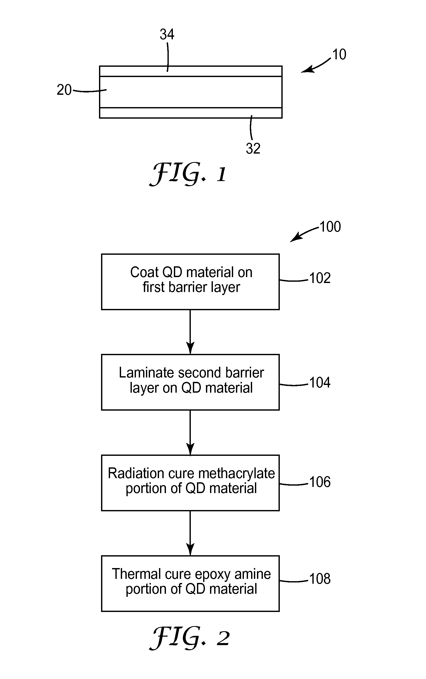
However, increased cure temperatures have been found to cause defects in the quantum dot films.
In addition, this polymer precurs

Method used


Image

  • Quantum dot film
  • Quantum dot film

Examples


example 1

[0039]Two types of solutions were prepared, one according to the current invention and one a control.

[0040]The components and amounts of the control solution, Solution A, are shown in Table 1. The control solution was thus an epoxy-only formulation. Epon 828 was a general purpose epoxy resin available from Momentive Specialty Chemicals (Columbus, Ohio). Part B was Epic RMX91B, a difuntional amine curative, (available from Epic Resins, Palmyra, Wis.) with a 15% white quantum dot concentrate (available from Nanosys Corp., Palo Alto, Calif.) which results in a final quantum dot concentration of 0.1 to 1 wt % in the cured epoxy quantum dot layer.

[0041]The components of Solution B, a hybrid epoxy / methacrylate formulation, are shown in Table 2. Three different versions of Solution B were prepared, each with a different methacrylate. The chosen methacrylates were SR348, SR540, and SR239, all from Sartomer USA, LLC (Exton, Pa.). Epon 824 was an epoxy resin available from Momentive Specialty...

example 2

[0045]Control Solution A was prepared as in Example 1. Solutions B through G were prepared as with the methacrylate solutions of Example 1 except that the methacrylate used was SR348 at six different levels ranging from 5% to 30% by weight. Components of all solutions are shown in Table 5.

TABLE 5Solution ASolution BSolution CSolution DSolution ESolution FSolution G%  0%  14%  30%  25%  20%  10%  5%MethacrylateSR348SR348SR348SR348SR348SR348SR348Epon 82465.0%55.6%45.2%48.4%51.7%58.2%61.4%SR34814.0%30.0%25.0%20.0%10.0%5.00%Darocur0.50%0.50%0.50%0.50%0.50%0.50%4265Part B35.0%29.9%24.3%26.1%27.8%31.3%33.1%Total100.0% 100.0% 100.0% 100.0% 100.0% 100.0% 100.0% 

[0046]The above solutions were mixed and coated between two 2 mil silicon release liners at a thickness of 50 micrometers with a knife coater as before, then UV and thermally cured as in Example 1. Water vapor transmission rates were measured as in Example 1. Results are shown in Table 6. Water vapor transmission properties were rela...

example 3

[0047]Two solutions were prepared to compare the peel strength performance of films with and without quantum dots.

[0048]Solution J was prepared with the proportions described in Table 7 below and was similar to previous formulations. Solution B was similar except that the Part B component was Epic RMX91B without the quantum dot concentrate The components of each solution are shown in Table 7. The two solutions were coated at 20 feet per minute on a pilot coater using a slot fed die with ¼ inch face and rear feed. Part A consisted of DER362 (diepoxy from Dow Chemical, Midland, Mich.), SR348 and Darocur 4265 and was fed via one pressure pot under nitrogen and Part B (the Epic RMX91B with or without quantum dots) was fed by another pressure pot, also under nitrogen. The two parts were fed into a static mixer before feeding into the die. The ratio of Part A to Part B was 2.3 to 1. Each solution was coated onto a 2 mil barrier film (previously described) and then immediately laminated to...


PUM

PropertyMeasurementUnit
Viscosityaaaaaaaaaa
Viscosityaaaaaaaaaa
Sizeaaaaaaaaaa

Abstract

A quantum dot film article includes a first barrier film, a second barrier film, and a quantum dot layer separating the first barrier from the second barrier film. The quantum dot layer includes quantum dots dispersed in a polymer material. The polymer material includes a methacrylate polymer, an epoxy polymer and a photoinitiator.

Description

FIELD[0001]The disclosure relates to quantum dot films and methods of forming quantum dot films having reduced defects.BACKGROUND[0002]Quantum dot films and elements are utilized in display and other optical constructions. The quantum dots need to be sealed from oxygen and water. Thus these quantum dots have been dispersed in a polymer such as an epoxy and sandwiched between two barrier films.[0003]During the formation of the quantum dot films the epoxy polymer is formed from a 2-part epoxy amine resin. Increasing the cure temperature is utilized to shorten the cure time of these epoxy polymers. However, increased cure temperatures have been found to cause defects in the quantum dot films. As the cure temperature increases, the polymer precursor viscosity decreases prior to the onset of cure. This low viscosity allows the polymer precursor to move within the laminate construction. In addition, this polymer precursor can move in response to stresses caused by barrier film shrinkage, ...

Claims


Application Information

Patent Timeline
IPC IPC(8): C09K11/02B32B27/08H01L33/50B32B7/12
CPCC09K11/025Y10T428/31515B32B27/08H01L33/501H01L33/505B32B2250/02B32B2250/24B32B2250/40B32B2255/10B32B2255/26B32B2264/102B32B2264/12B32B2264/10B32B2307/712B32B2307/7244B32B2307/7246B32B2307/7265B32B2457/20Y10S977/774Y10S977/783Y10S977/892Y10S977/932B82Y20/00B82Y40/00Y10T428/25B32B7/12B32B27/36B32B2551/00C09K11/02C09K11/565C09K11/883H01L33/502
Inventor NELSON, ERIC W.ECKERT, KARISSA L.KOLB, WILLIAM BLAKENESVIK, TYLER D.TU, MINGHU
Owner 3M INNOVATIVE PROPERTIES CO
Why Eureka
Try Eureka