
System and methods for refueling a vehicle

a vehicle and system technology, applied in the direction of liquid handling, electrical control, packaged goods type, etc., can solve the problems of engine stalling, unusable, engine stalling, etc., and achieve the effect of reducing the release of fuel vapors

Inactive Publication Date: 2015-12-24
FORD GLOBAL TECH LLC
View PDF3 Cites 9 Cited by
  • Summary
  • Abstract
  • Description
  • Claims
  • Application Information

AI Technical Summary

Benefits of technology

The patent text describes a system and method for refueling and controlling emissions in fuel systems of hybrid-electric vehicles. The technical effects of the patent include reducing the cost and complexity of the fuel system by using a single vacuum pump to slowly depressurize the fuel tank without requiring a multi-stage fuel tank isolation valve, and controlling the rate of depressurization via a changeover valve and opening of the fuel tank isolation valve. Additionally, the patent describes a method for refueling while controlling emissions by opening the fuel tank isolation valve and fluidly coupling the fuel vapor canister to atmosphere via a deactivated vacuum pump. The system also includes an evaporative leak check module with a vacuum pump and changeover valve for performing reference checks, fuel system evacuation leak checks, and purge operations.

Problems solved by technology

However, opening the FTIV when a significant pressure exists within the fuel tank may result in the corking of other fuel tank valves such as a grade vent valve and / or a fill limit vent valve, rendering them unusable.
Depressurizing the fuel tank in this fashion could also lead to an abundance of hydrocarbons entering the engine intake system, altering the air / fuel ratio, and potentially leading to engine stalling.
Additionally, any delays or imprecision in control of an FTIV may increase release of hydrocarbons or degraded air-fuel ratio control during purging.
Further a loud hissing noise may occur as the fuel tank is depressurized in a single stage.
Dual stage FTIVs with multiple sized orifices, or the use of multiple valves in parallel have been described, but these configurations may add complexity to a system, and may increase the difficulty of diagnosing malfunctions within the system.

Method used


Image

  • System and methods for refueling a vehicle
  • System and methods for refueling a vehicle
  • System and methods for refueling a vehicle

Examples


Embodiment Construction

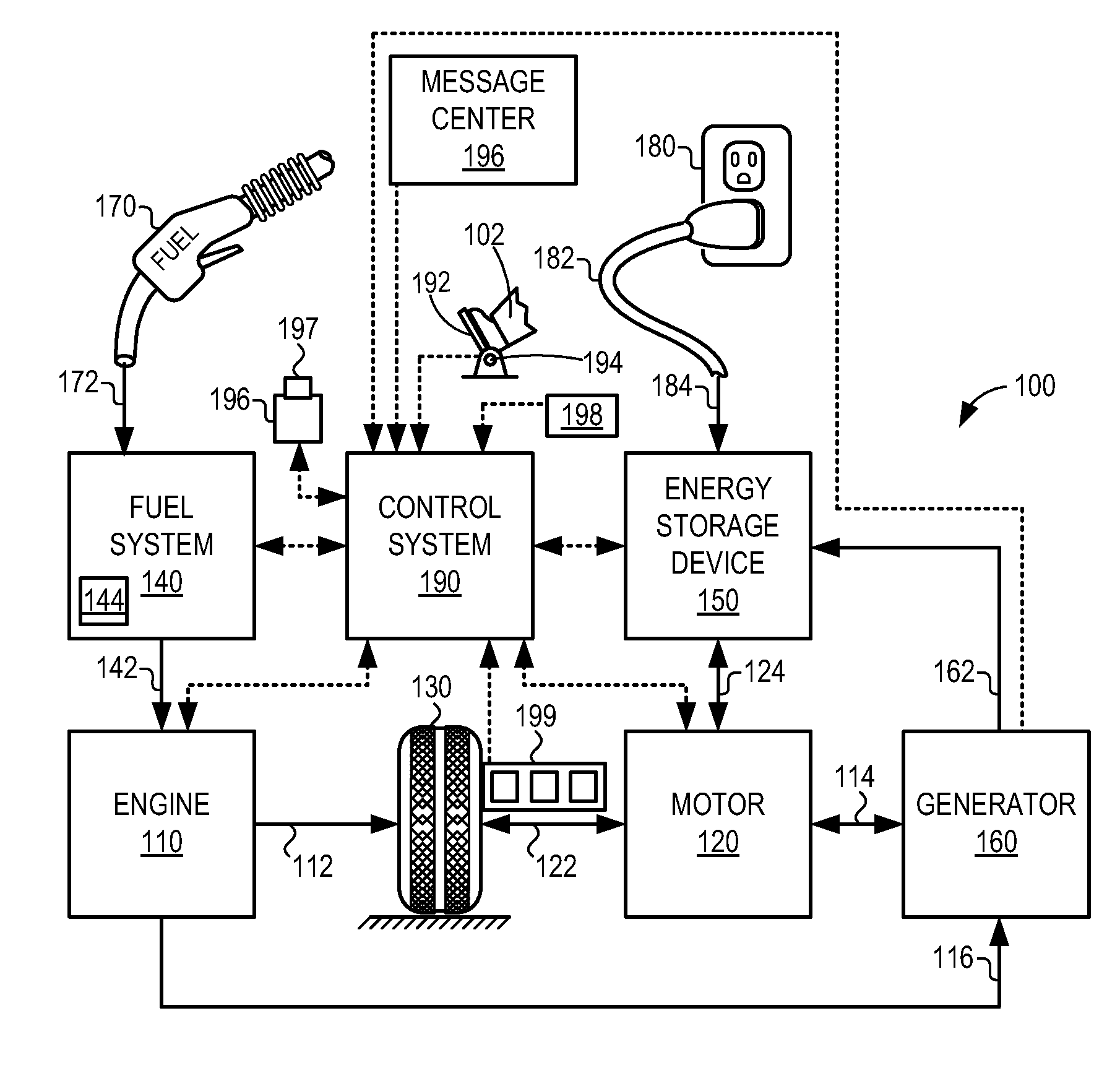
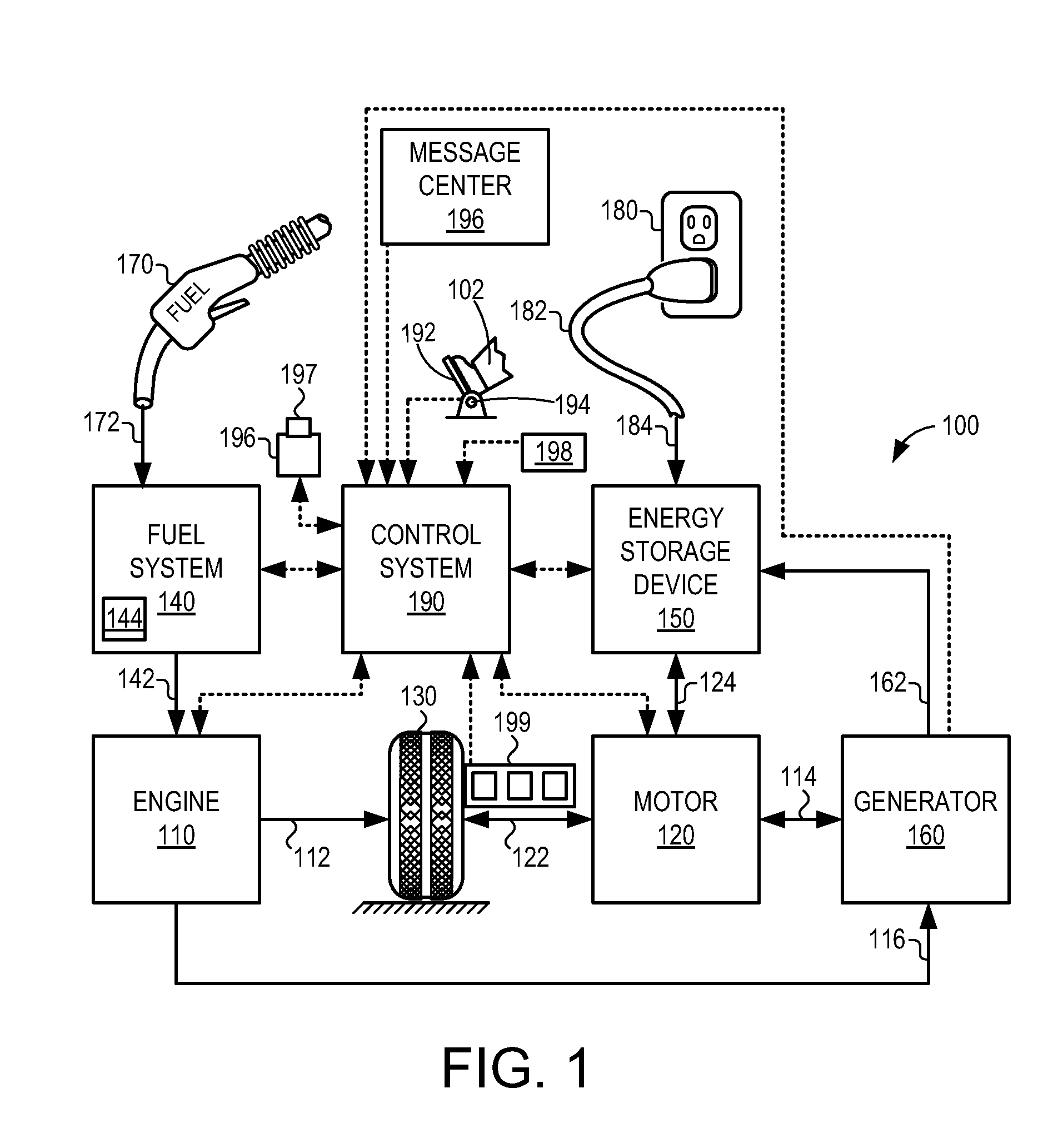
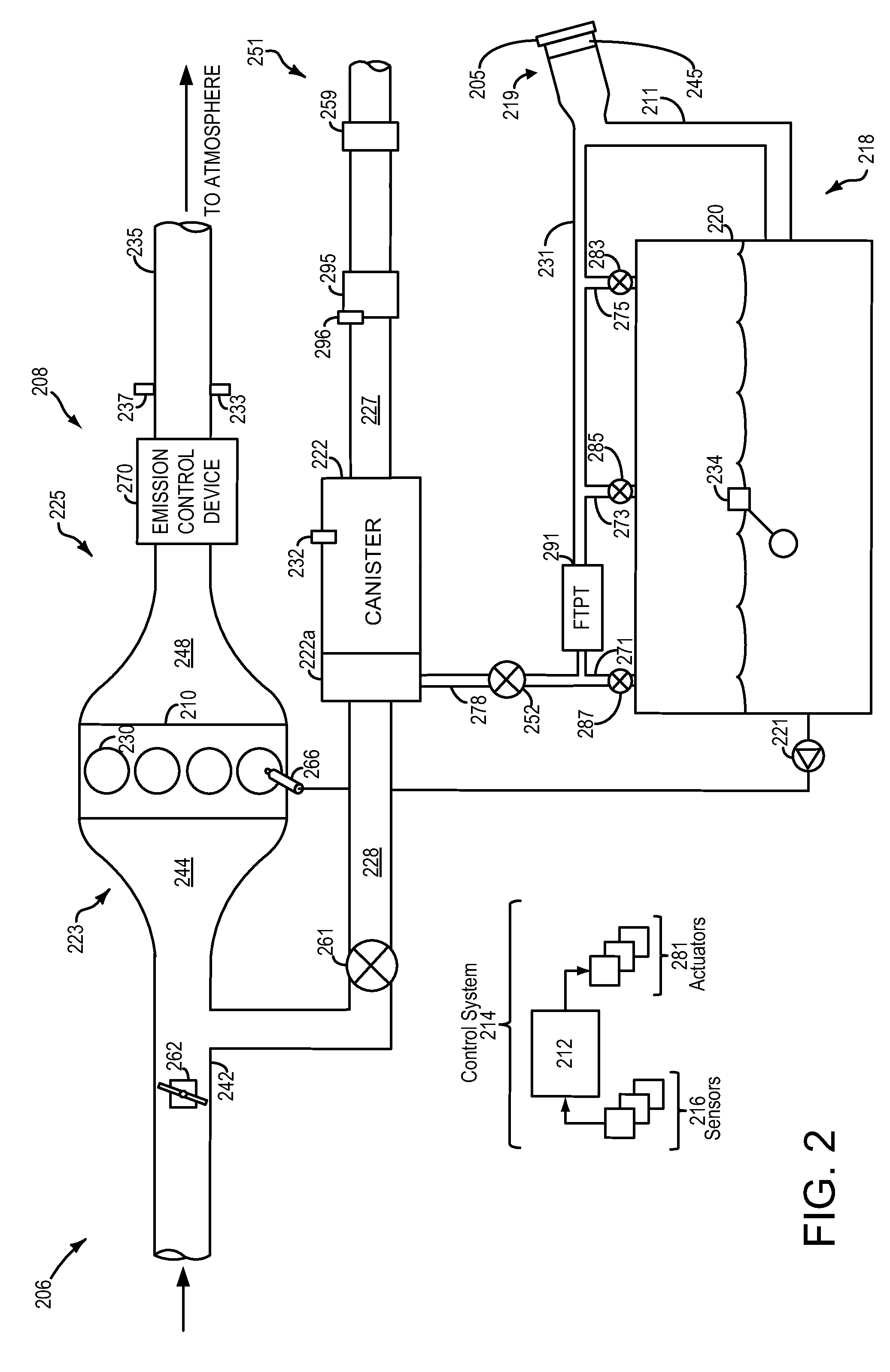
[0017]This detailed description relates to systems and methods for refueling a vehicle. In particular, the description relates to systems and methods for depressurizing a fuel tank with a single stage fuel tank isolation valve via controlled depressurization. A refueling event may take place in a hybrid vehicle, such as the hybrid vehicle schematically depicted in FIG. 1. The hybrid vehicle may comprise a fuel system and evaporative emissions system, as depicted in FIG. 2. The hybrid vehicle may further comprise an evaporative leak check module (ELCM), comprising a vacuum pump and changeover valve (COV) operable to various configurations, as shown in FIGS. 3A-3D. During the fuel tank depressurization, the ELCM may be positioned to restrict air flow, thereby controlling the rate of depressurization, as shown by the method depicted in FIG. 4. FIG. 5 shows an example timeline for a refueling event using the method of FIG. 4.

[0018]FIG. 1 illustrates an example vehicle propulsion system ...


PUM


Abstract

A method for a fuel system, comprising: during a first condition, fluidly coupling a fuel tank to a fuel vapor canister; and fluidly coupling the fuel vapor canister to atmosphere via a deactivated vacuum pump. By fluidly coupling the fuel vapor canister to atmosphere via a deactivated vacuum pump, the fuel tank may be depressurized slowly without requiring a multi-stage or multi-valve fuel tank isolation system. In this way, the cost and complexity of the fuel system is reduced.

Description

BACKGROUND AND SUMMARY[0001]Vehicle fuel systems include evaporative emission control systems designed to reduce the release of fuel vapors to the atmosphere. For example, vaporized hydrocarbons (HCs) from a fuel tank may be stored in a fuel vapor canister packed with an adsorbent which adsorbs and stores the vapors. At a later time, when the engine is in operation, the evaporative emission control system allows the vapors to be purged into the engine intake manifold for use as fuel.[0002]In hybrid-electric vehicles, the fuel tank is typically sealed with a fuel tank isolation valve (FTIV). Prior to refueling, fuel vapors in the tank may be vented to the fuel vapor canister by opening the FTIV. When the fuel tank pressure reaches a safe level, access to the fuel filler neck may be granted, through unlocking a refueling door, for example.[0003]However, opening the FTIV when a significant pressure exists within the fuel tank may result in the corking of other fuel tank valves such as ...

Claims


Application Information

Patent Timeline
Patent Type & Authority Applications(United States)
IPC IPC(8): F02D41/00F17C5/02F16K21/18F02M25/08
CPCF02D41/0032F02M25/0836F17C2227/04F17C5/02F16K21/18F02M25/0818F02D41/042
Inventor DUDAR, AED M.
Owner FORD GLOBAL TECH LLC
Learn More