Dynamic light scattering measurement device and dynamic light scattering measurement method

Inactive Publication Date: 2015-12-24
OTSUKA DENSHI CO LTD +1
View PDF3 Cites 5 Cited by
  • Summary
  • Abstract
  • Description
  • Claims
  • Application Information

AI Technical Summary

Benefits of technology

[0005]Several aspects of the invention may provide a dynamic light scattering measurement device and a dynamic light scattering measurement method that suppress

Problems solved by technology

According to the known dynamic light scattering measurement device, however, since the reference light and sample light (scattered light from the sample) propagate through different (indepen

Method used


Image

  • Dynamic light scattering measurement device and dynamic light scattering measurement method
  • Dynamic light scattering measurement device and dynamic light scattering measurement method
  • Dynamic light scattering measurement device and dynamic light scattering measurement method

Examples


first embodiment

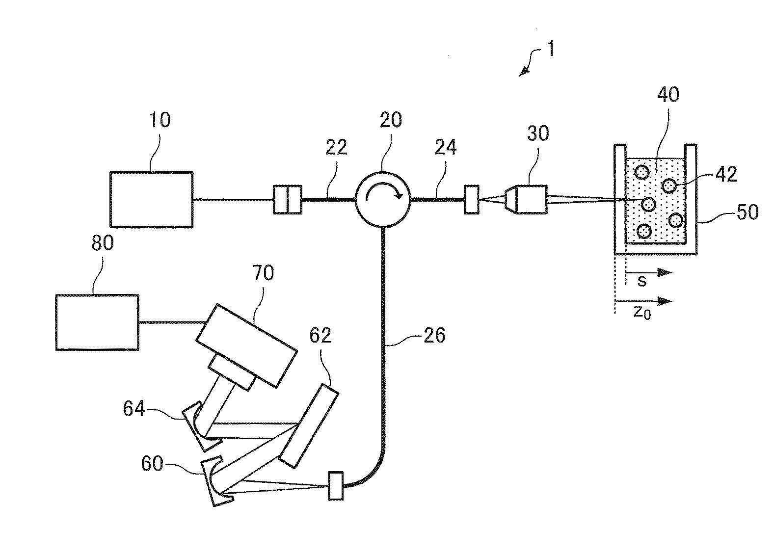
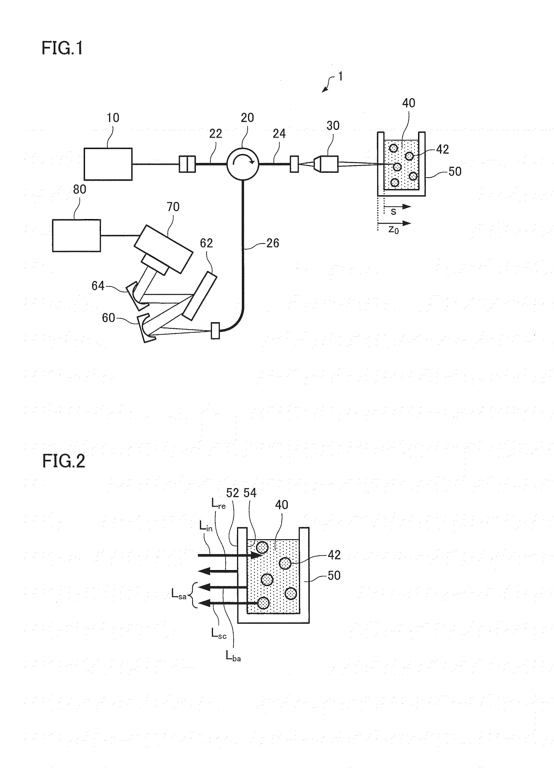
[0045]FIG. 1 is a schematic diagram illustrating a configuration of a dynamic light scattering measurement device according to a first embodiment of the invention.

[0046]A dynamic light scattering measurement device 1 includes a low-coherence light source 10, an optical circulator 20, an objective lens 30, a diffraction grating 62, a photodetector 70, and a calculation section 80, the objective lens 30 functioning as an irradiation section, the diffraction grating 62 and the photodetector 70 functioning as a spectral intensity acquisition section, and the calculation section 80 functioning as a measurement section.

[0047]A superluminescent diode (SLD) is used as the low-coherence light source 10, for example. Note that another low-coherence light source or an ultrashort coherence light source (e.g., white LED) may also be used as the low-coherence light source 10.

[0048]The optical circulator 20 is a three-port optical circulator that has a first port to which an optical fiber 22 is co...

second embodiment

[0069]FIG. 10 is a schematic diagram illustrating a configuration of a dynamic light scattering measurement device according to a second embodiment of the invention. In FIG. 10, the same elements as those illustrated in FIG. 1 are indicated by the same reference signs (symbols), and descriptions thereof are appropriately omitted.

[0070]The dynamic light scattering measurement device 1 illustrated in FIG. 10 is configured so that light emitted from the low-coherence light source 10 is incident on the objective lens 30 through the optical fiber 22, the optical circulator 20, and the optical fiber 24, and applied vertically to a gas-liquid interface 44 (i.e., the interface between the gaseous atmosphere (air) and the sample 40 (i.e., the surface of the sample 40)) of the sample 40 through an upper opening of the sample cell 50. The sample cell 50 is disposed so that the gas-liquid interface 44 and the sample 40 (measurement target range) are included within the depth of focus (through t...

third embodiment

[0073]FIG. 12 is a schematic diagram illustrating a configuration of a dynamic light scattering measurement device according to a third embodiment of the invention. In FIG. 12, the same elements as those illustrated in FIG. 1 are indicated by the same reference signs (symbols), and descriptions thereof are appropriately omitted.

[0074]In the dynamic light scattering measurement device 1 illustrated in FIG. 12, a GRIN lens 32 (gradient-index lens) is connected to the end of the optical fiber 24 that is situated on the side of the sample 40. The GRIN lens 32 is a cylindrical lens that has flat end faces, and has a refractive index distribution in the radial direction. A half mirror 34 (e.g., evaporated metal film) is provided to the exit-side end face of the GRIN lens 32 (i.e., the exit-side end of an optical propagation member). In FIG. 12, the distance z0 is the distance from the exit-side end face (half minor 34) of the GRIN lens 32 to the center (scattering point) of each particle ...


PUM


Abstract

A dynamic light scattering measurement device includes an irradiation section that applies light emitted from a low-coherence light source to a sample that includes particles, a spectral intensity acquisition section that disperses reflected light from a reference plane and scattered light from the sample that has passed through the reference plane to acquire a spectral intensity of interference light of the reflected light and the scattered light, the reference plane being situated to intersect an optical path through which the light is applied to the sample, and a measurement section that measures dynamic light scattering of the sample based on the acquired spectral intensity.

Description

[0001]Japanese Patent Application No. 2014-127259, filed on Jun. 20, 2014, is hereby incorporated by reference in its entirety.BACKGROUND OF THE INVENTION[0002]The present invention relates to a dynamic light scattering measurement device and a dynamic light scattering measurement method.[0003]WO2013 / 077137 discloses a dynamic light scattering measurement device that utilizes a low-coherence light source and a Michelson interferometer. The dynamic light scattering measurement device disclosed in WO2013 / 077137 acquires the spectral intensity of interference light of reference light and scattered light, and performs a dynamic light scattering measurement based on the acquired spectral intensity, thereby making it unnecessary to perform scanning with a reference mirror (reference plane).[0004]According to the known dynamic light scattering measurement device, however, since the reference light and sample light (scattered light from the sample) propagate through different (independent) ...

Claims


Application Information

Patent Timeline
IPC IPC(8): G01N21/51G01N21/03
CPCG01N21/51G01N2201/062G01N21/0303G01J3/0205G01J3/0208G01J3/021G01J3/0218G01J3/18G01J3/4412G01J9/02G01J2009/0223G01N15/0211G01N21/45G01N2015/0222G01N2021/0389G01N2021/4709
Inventor IZUTANI, YUSUKEIWAI, TOSHIAKI
Owner OTSUKA DENSHI CO LTD
Why Eureka
Try Eureka