Cell cooling frames with cantilevered side seals

Inactive Publication Date: 2015-12-24
GM GLOBAL TECH OPERATIONS LLC
View PDF4 Cites 0 Cited by
  • Summary
  • Abstract
  • Description
  • Claims
  • Application Information

AI Technical Summary

Benefits of technology

The present invention addresses the problem of high costs and complexity during battery pack assembly caused by the inclusion of multiple components and reduced assembly tolerances. The invention provides a modular design that simplifies the assembly process by allowing for clearance between the battery cells and cooling frame during high-speed automated assembly, and then closing this gap once the frame and cell are connected. The invention also includes a method of automatic sealing between the battery cell and the cooling frame using resiliently-biased sealing members, which results in a flat sealing surface between the frame and cell that prevents airflow sealing issues and allows for gap-free cell-to-cooling frame contact after assembly. Overall, the invention simplifies and streamlines the battery pack assembly process, reduces costs, and improves assembly quality.

Problems solved by technology

Traditionally, all of these components are stacked and joined together in such a way that weight, cost and complexity are increased.
By way of example, the frames alone may be as much as 10% of the total weight of the overall battery pack assembly or system, while the inclusion of cooling and sealing functions may significantly add to assembly operation complexity.

Method used


Image

  • Cell cooling frames with cantilevered side seals
  • Cell cooling frames with cantilevered side seals
  • Cell cooling frames with cantilevered side seals

Examples


Embodiment Construction

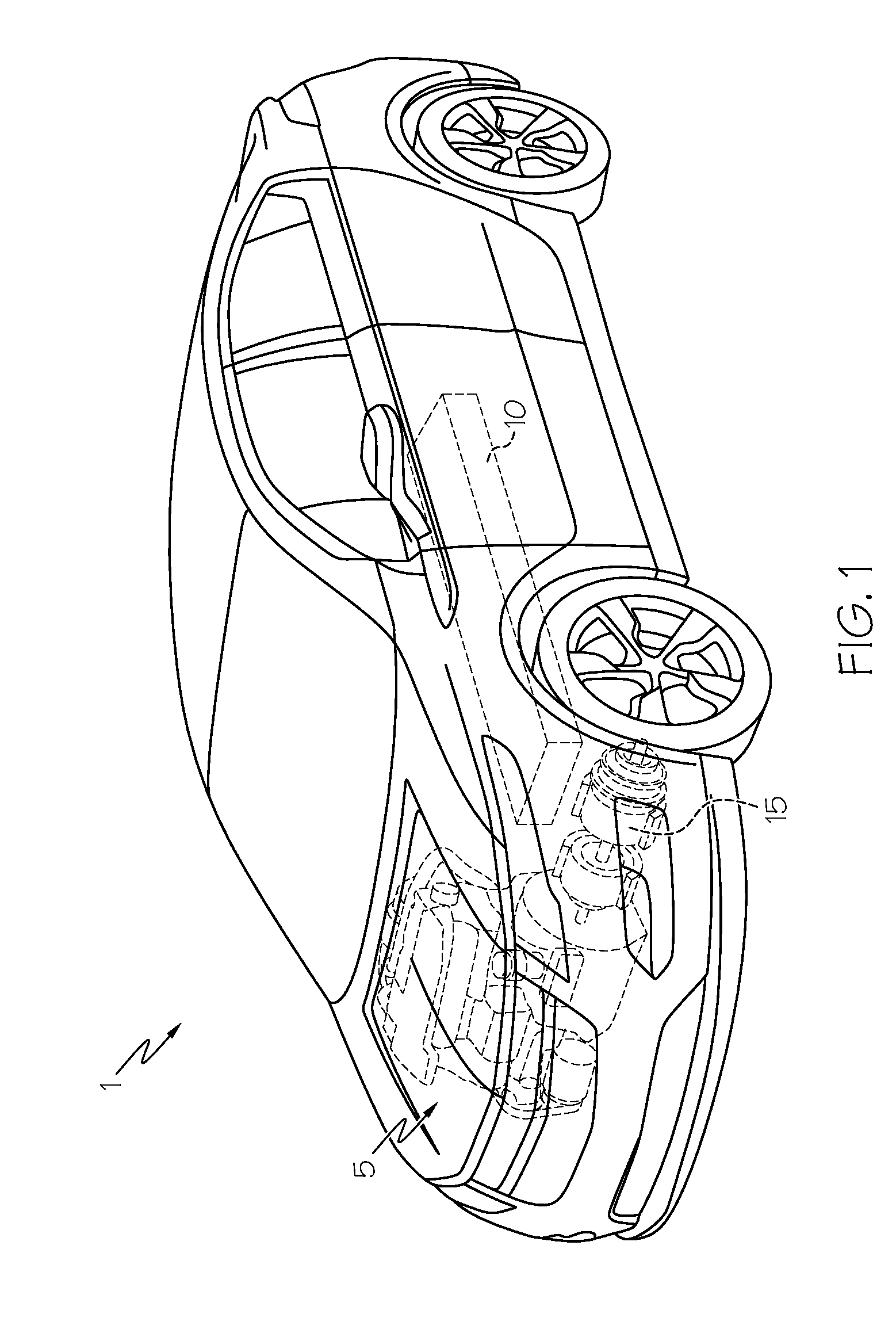
[0018]Referring first to FIG. 1, a vehicle 1 includes a hybrid propulsion system in the form of an electric power source made up of a conventional ICE 5 and a battery pack 10, both cooperative with an electric motor 15. Such a vehicle is known as a hybrid electric vehicle (HEV). It will be appreciated by those skilled in the art that vehicle 1 may not require an ICE 5, in such case, rather than being an HEV, it is an electric vehicle (EV); either form is within the scope of the present invention. Additional drivetrain components (none of which are shown) useful in providing propulsive power to one or more of the wheels and coupled to one or both of the battery pack 10 and ICE 5 are understood to include rotating shafts, axles, transmission, controllers or the like. While vehicle 1 is presently shown as a car, the applicability of the hybrid propulsion system to other such automotive forms (including trucks, buses, aircraft, watercraft, spacecraft and motorcycles) is deemed to be wit...


PUM

PropertyMeasurementUnit
Forceaaaaaaaaaa
Shapeaaaaaaaaaa
Dimensionaaaaaaaaaa

Abstract

A modular battery pack and method of making a battery pack. Prismatic can battery cells are interspersed with cooling frames along a stacking axis within a housing such that numerous a cell-frame assemblies, each with a cooling path, are formed. Resiliently-biased sealing members on the frames are arranged such that they remain out of the way of a footprint defined by the joined cells and frames to promote ease of high-speed cell-to-frame assembly. Upon formation of the cell-frame assembly and subsequent placement into the housing with inner walls that press against the protruding ends of the sealing member, the sealing member is forced by the housing to come into contact engagement with a corresponding surface of the edge of the battery cell. The generally linear, planar contact surface formed by the contact engagement promotes the formation of a sealing surface that makes it harder for introduced cooling air to escape. By this sealing member construction, cell-frame assemblies may be produced with high-speed automated assembly techniques that may have both large manufacturing tolerances prior to assembly and substantially gap-free cell-to-cooling frame contacting surfaces after assembly.

Description

BACKGROUND OF THE INVENTION[0001]This invention relates generally to cooling structure for battery cells within a battery pack, and more particularly to coupling a battery cell to a cooling frame with integral attachment features to simultaneously promote adequate clearance between the cell and frame during high volume battery pack assembly and sealing of a fluid introduced into a space defined between the cell and the cooling frame once the battery pack has been assembled.[0002]Lithium-ion and related batteries, collectively known as a rechargeable energy storage system (RESS), are being used in automotive and related transportation applications as a way to supplement, in the case of hybrid electric vehicles (HEVs), or supplant, in the case of purely electric vehicles (EVs), conventional internal combustion engines (ICEs). The ability to passively store energy from stationary and portable sources, as well as from recaptured kinetic energy provided by the vehicle and its components,...

Claims


Application Information

Patent Timeline
IPC IPC(8): H01M10/65H01M2/10H01M50/183H01M50/209H01M50/249
CPCH01M10/647H01M10/625H01M10/613Y10T29/49909H01M10/6555H01M10/6561H01M2/1077H01M50/183B60L50/64H01M50/249H01M50/209Y02E60/10
Inventor MCLAUGHLIN, BARTON W.MCCLURE, CHARLES W.OURY, ANDREW P.
Owner GM GLOBAL TECH OPERATIONS LLC
Why Eureka
Try Eureka