Ultrasound imaging system and method

a technology of ultrasound imaging and ultrasound, applied in ultrasonic/sonic/infrasonic image/data processing, tomography, applications, etc., can solve the problems of only determining the total mass of the selected tissue, other state of the art modalities are too inconsistent to provide meaningful data, and poor physical fitness, etc., to achieve convenient and convenient operation, precise, reliable, fast and cost-effective measurement

Inactive Publication Date: 2015-12-31
KONINKLJIJKE PHILIPS NV
View PDF4 Cites 10 Cited by
  • Summary
  • Abstract
  • Description
  • Claims
  • Application Information

AI Technical Summary

Benefits of technology

[0008]It is an object of the present invention to provide a device for ultrasound imaging that particularly allows a precise, reliable, fast and cost-effective measurement of tissue layer boundaries within an examination object. Preferably, sa...

Problems solved by technology

Low levels of physical activity and bad dietary habits can lead to poor physical fitness and in the long run result in lifestyle-related diseases such as diabetes, hypertension, dyslipidemia, polycystic ovary syndrome, reproductive abnormalities, sexual dysfunction, heart disease and metabolic syndrome.
Other state of the art modalities are too inconsistent to provide meaningful data, such as e.g. bioelectrical impedance, which is very sensitive to the varying amount of water in the body.
Furthermore, these techniques are only capable of determining total mass of the selected tissue and do not provide ins...

Method used


Image

  • Ultrasound imaging system and method
  • Ultrasound imaging system and method
  • Ultrasound imaging system and method

Examples


Embodiment Construction

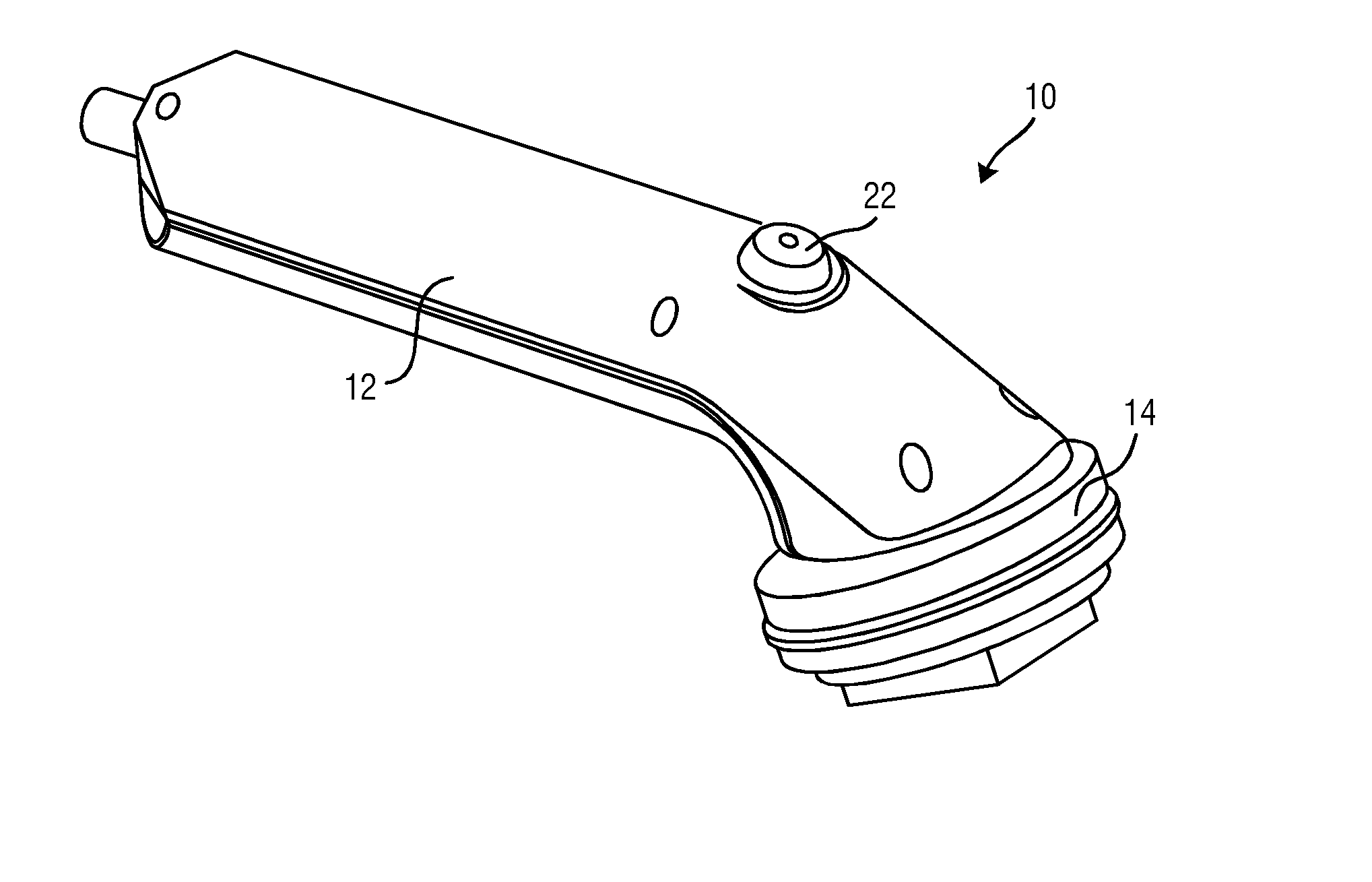
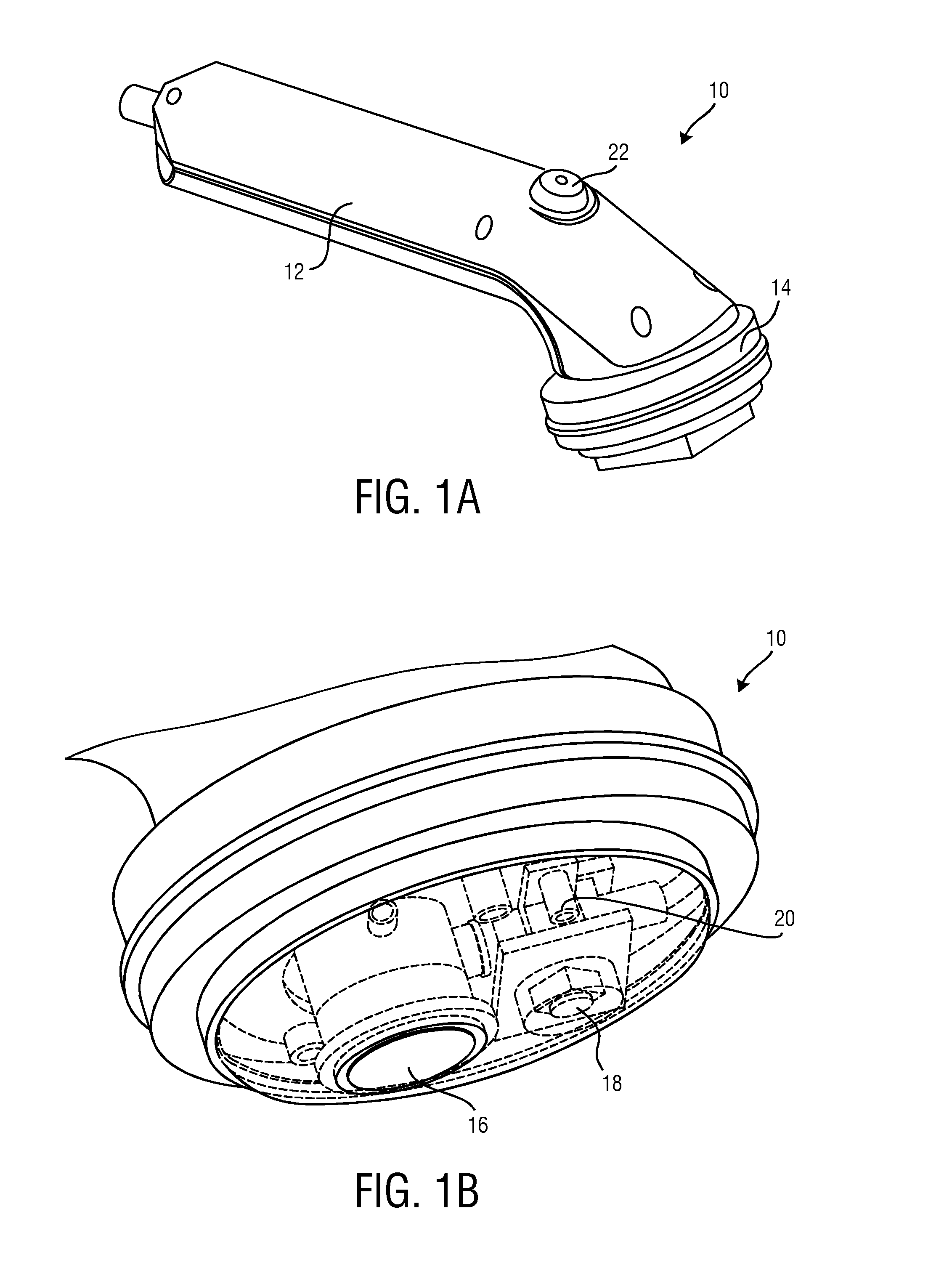
[0066]FIG. 1 shows an embodiment of an ultrasound probe 10 of the ultrasound imaging system 100 in two different perspectives. The ultrasound probe 10 is in FIG. 1A shown in its entirety. FIG. 1B shows the head of the ultrasound probe 10 from below. The ultrasound probe 10 comprises a handle 12 and a probe head 14. The probe head 14 in this case has a substantially circular shape. The shape of the probe head 14 may, however, deviate from the illustrated shape without leaving the scope of the invention.

[0067]The probe head 14 comprises an ultrasound transducer element 16, a movement sensor 18 and a pressure sensor 20. The ultrasound transducer element 16 is according to the present invention preferably realized as a single element ultrasound transducer 16. This single element ultrasound transducer 16 transmits and receives ultrasound signals. An actuation button 22 may be integrated in the handle 12. This actuation button 22 enables to start and stop the signal acquisition.

[0068]The ...


PUM


Abstract

The present invention relates to an ultrasound imaging system (100) comprising: an ultrasound probe (10) that comprises a single element ultrasound transducer (16) for transmitting an receiving ultrasound signals; a movement sensor (18) for sensing a displacement-over-time signal x(t) of a displacement (x) of the ultrasound probe (10) relative to an examination object (24) during signal acquisition; an image acquisition hardware (26) that is configured to reconstruct an M-mode ultrasound image from the received ultrasound signals, said reconstructed M-mode ultrasound image being a two-dimensional image I(t,y) comprising multiple one-dimensional depth signals of substantially constant depth (y) in the examination object (24) illustrated over time (t), wherein the image acquisition hardware (26) is further configured to map said M-mode ultra-sound image I(t,y) to a two-dimensional second image I(x,y) comprising the depth signals illustrated over the displacement (x) by using the displacement-over-time signal x(t) that is sensed with the movement sensor (18); and an image analysis unit (48) that is configured to analyse said second image and to detect at least one tissue layer boundary of the examination object (24) in said second image.

Description

FIELD OF THE INVENTION[0001]The present invention relates to an ultrasound imaging system. The present invention particularly relates to an ultrasound imaging system for detecting tissue layer boundaries within an examination object. Further, the present invention relates to a method for detecting at least one tissue layer boundary of an examination object. Still further, the present invention relates to a corresponding computer program for implementing the method.BACKGROUND OF THE INVENTION[0002]In the field of performance sports, personal fitness and health care appliances it is desirable to get insight into a body's proportional composition of different tissue types. For this purpose it is necessary to distinguish several main tissues from each other. The most important tissues to detect from a health perspective are: fat mass and fat-free mass, lean body mass and muscle mass and a further discrimination of subcutaneous adipose tissue (SAT) and visceral adipose tissue (VAT). The ...

Claims


Application Information

Patent Timeline
IPC IPC(8): A61B8/08A61B8/00A61B8/14
CPCA61B8/0858A61B8/4254A61B8/429A61B8/4444A61B8/5207A61B8/5223A61B5/4872A61B8/4483A61B8/14A61B8/5246G16H50/30
Inventor SHAN, CAIFENGZUO, FEI
Owner KONINKLJIJKE PHILIPS NV
Why Eureka
Try Eureka