
Bearing Grease

a technology of bearings and grease, applied in the direction of cleaning with liquids, lighting and heating apparatus, separation processes, etc., can solve the problems of contributing to further wear and damage, difficult etc., and achieve the effect of slow rotation speed of rotors, easy use, and easy to achieve effective lubrication

Active Publication Date: 2015-12-31
INSIGHT ANALYTICS SOLUTIONS HLDG LTD
View PDF0 Cites 6 Cited by
  • Summary
  • Abstract
  • Description
  • Claims
  • Application Information

AI Technical Summary

Benefits of technology

The invention provides a method for replacing grease in a wind turbine with a new flushing cover that has holes to access the main bearing. The method involves spraying a cleaning fluid onto the bearing to remove grease, and then pumping the cleaning fluid out of the housing. The main technical effect of this invention is a more efficient and effective way of replacing grease in wind turbines, which results in reduced downtime and improved maintenance.

Problems solved by technology

Effective lubrication difficult to achieve because of the slow rotation speeds of the rotor and the wide ranges of operating temperature.
This means that debris from bearing wear does not escape from the bearing, and will contribute to further wear and damage.

Method used


Image

  • Bearing Grease
  • Bearing Grease
  • Bearing Grease

Examples


Embodiment Construction

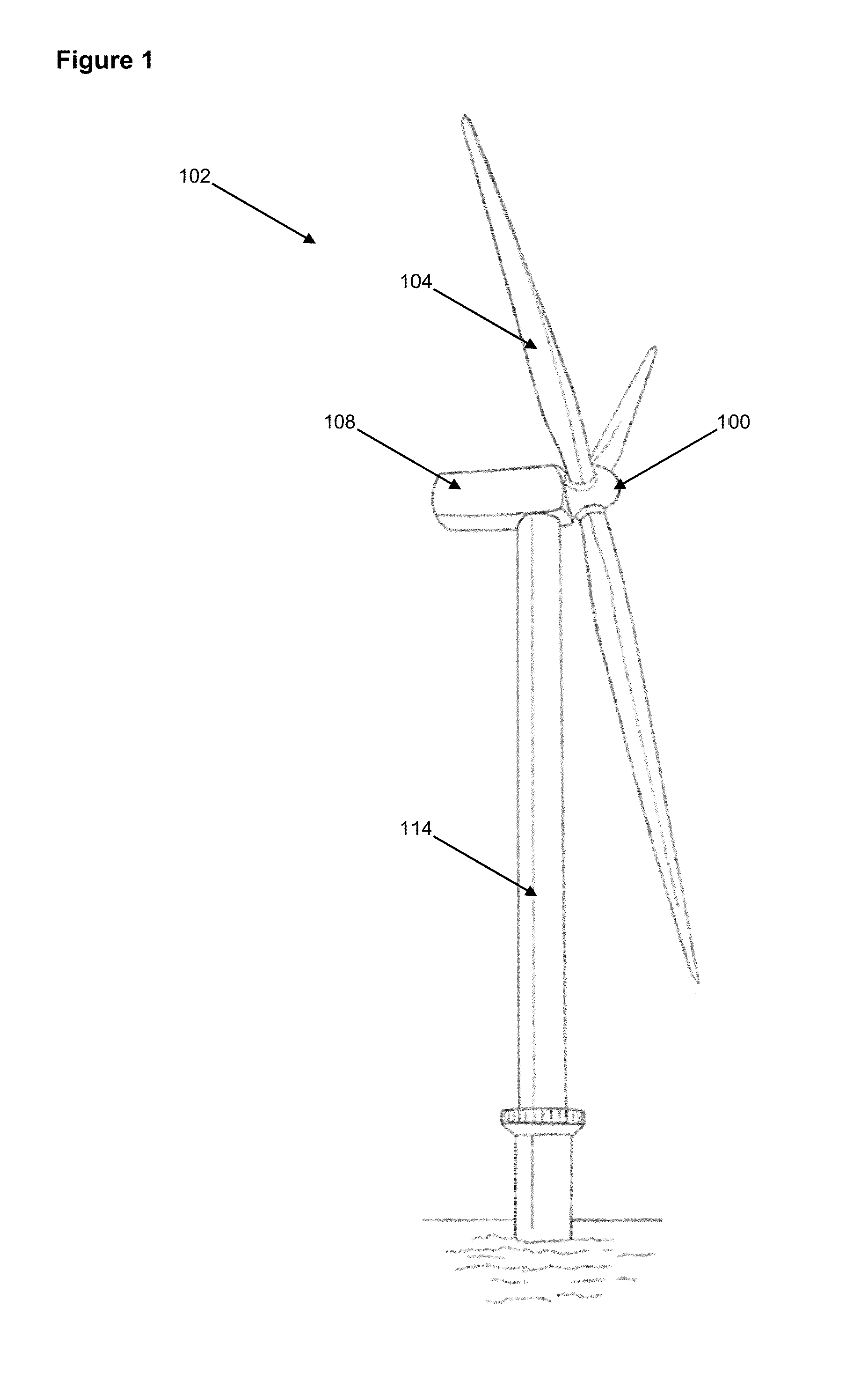
[0017]FIG. 1 is a perspective view of an example of a wind turbine. Although an offshore wind turbine is shown, it should be noted that the description below may be applicable to other types of wind turbines. The wind turbine 102 includes rotor blades 104 mounted to a hub 100, which is supported by a nacelle 108 on a tower 114.

[0018]Wind causes the rotor blades 104 and hub 106 to rotate about a main axis. This rotational energy is delivered to a main shaft, which is part of a power transmission system housed within the nacelle 108. The main shaft is supported by a bearing arrangement within a bearing housing. The bearing housing is attached to a mainframe (not shown) via bolts. An upwind and a downwind bearing cover are attached to the bearing housing via fastener means.

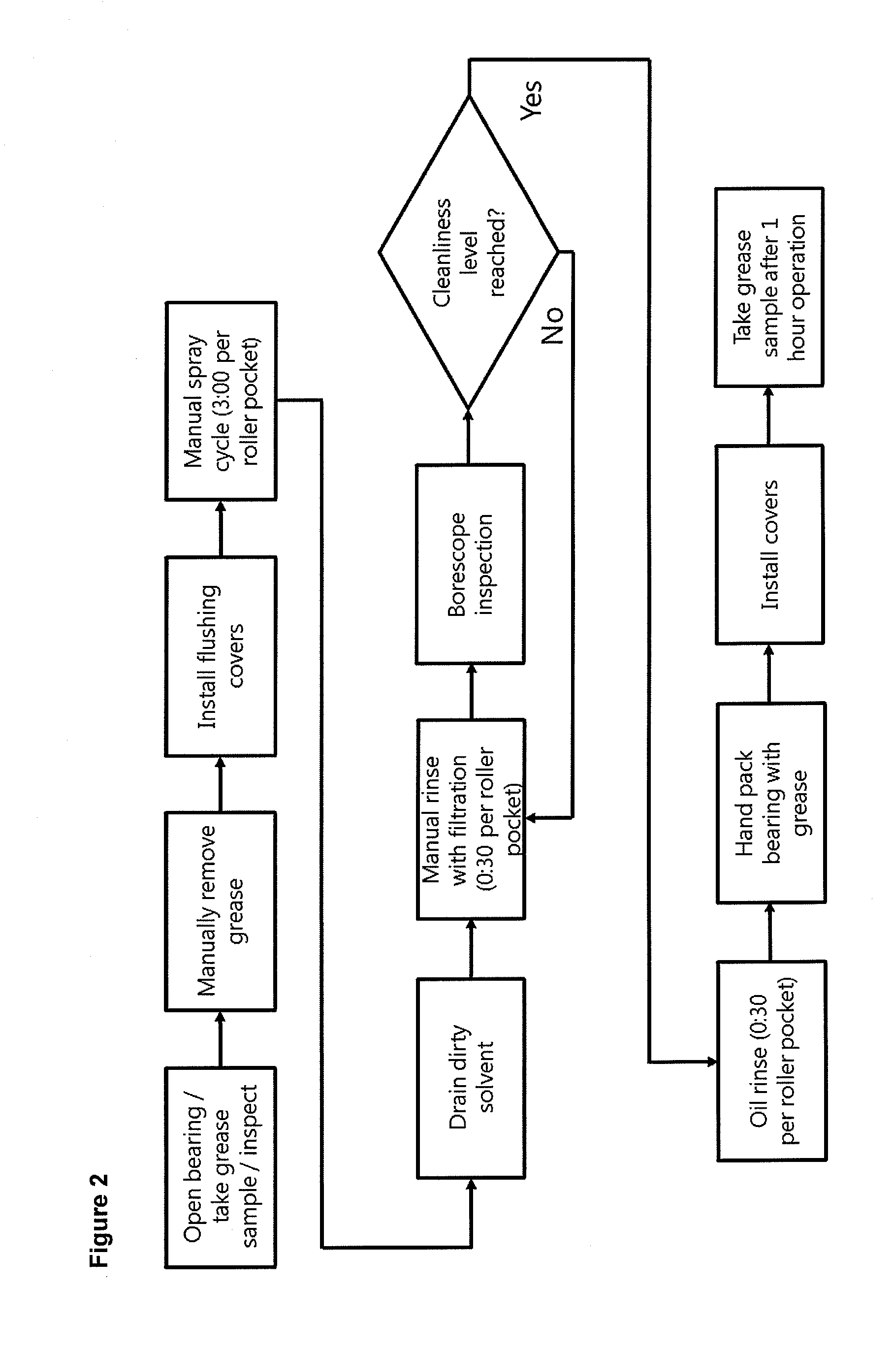
[0019]FIG. 2 shows a method for performing a main bearing flush, in which the grease in a main bearing of a wind turbine is replaced, for example, when maintenance or inspection is required. In a first step, the bear...


PUM

PropertyMeasurementUnit
Fractionaaaaaaaaaa
Volumeaaaaaaaaaa
Volumeaaaaaaaaaa

Abstract

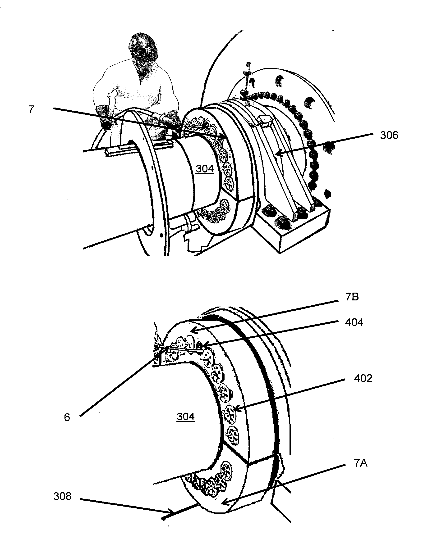
A method is disclosed for replacing grease in a main bearing of a wind turbine, the main bearing located in a housing and the housing having least one cover plate. the bearing cover plate is removed from the housing, grease is manually removed from the main bearing, and a flushing cover is installed on the housing in place of the bearing cover plate. The flushing cover has at least two parts, the parts fitting around the main shaft, and each part having a seal so that when its attached to the bearing housing, the flushing cover forms a seal with the main shaft. The flushing cover has holes allowing access to the main bearing, and a solvent or oil is sprayed via one of the holes onto the main bearing to remove grease, the remaining holes being sealed by a removable plug. Solvent or oil is pumped out of the housing via a port at the bottom of the housing or flushing cover. The process is repeated for each hole, and the flushing cover removed, the main bearing packed with grease, and the bearing cover plate re-affixed. The spraying step involves pumping solvent or oil from a reservoir to the spray nozzle, and the step of pumping solvent or oil out of the bearing housing involves pumping solvent or oil to the reservoir via a return hose. This means that the solvent or oil is recycled during the replacing of the grease. An apparatus for flushing grease from a main bearing of a wind turbine is also described.

Description

BACKGROUND OF THE INVENTION[0001]The present invention relates to improvements to the lubrication of wind turbine main bearings. In particular it relates to the flushing of grease from a wind turbine main bearing during replacement of the grease during maintenance.BRIEF SUMMARY OF THE INVENTION[0002]Wind or water turbine main bearing are typically formed of roller bearings. Effective lubrication difficult to achieve because of the slow rotation speeds of the rotor and the wide ranges of operating temperature. Grease lubrication is widely used for such bearings, and its consistency prevents it from leaking out of the bearing, makes it easy to use, and gives it good sealing properties. However packed grease does not move around within the bearing arrangement under typical turbine operating conditions. This means that debris from bearing wear does not escape from the bearing, and will contribute to further wear and damage.[0003]The present invention provides apparatus and methods for r...

Claims


Application Information

Patent Timeline
IPC IPC(8): F16C33/66B08B3/10B01D35/02B08B3/02
CPCB08B9/00B01D35/02B08B3/02B08B3/10F03D80/70F03D80/50F16C2360/31F03D80/55Y02E10/722F16C33/6622Y02E10/72F05B2240/50F16C19/00F16C2235/00
Inventor SMITH, RICHARDCROWTHER, ASLEYGRAETER, JESSE HARRIESMACINDOE, SCOTTHORNEMANN, MICHAEL ULFERT
Owner INSIGHT ANALYTICS SOLUTIONS HLDG LTD
Learn More