
MEMS angular inertial sensor operating in tuning fork mode

a technology of angular inertial sensor and tuning fork, which is applied in the direction of acceleration measurement using interia force, instruments, devices using electric/magnetic means, etc. it can solve the problems of energy loss persisting in such sensors and the performance of such sensors may be degraded, and achieve good separation and high coupling stiffness

Active Publication Date: 2015-12-31
THALES SA
View PDF1 Cites 17 Cited by
  • Summary
  • Abstract
  • Description
  • Claims
  • Application Information

AI Technical Summary

Benefits of technology

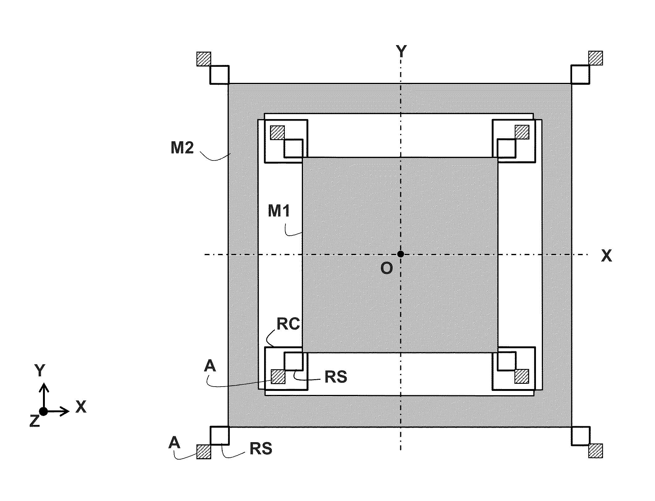
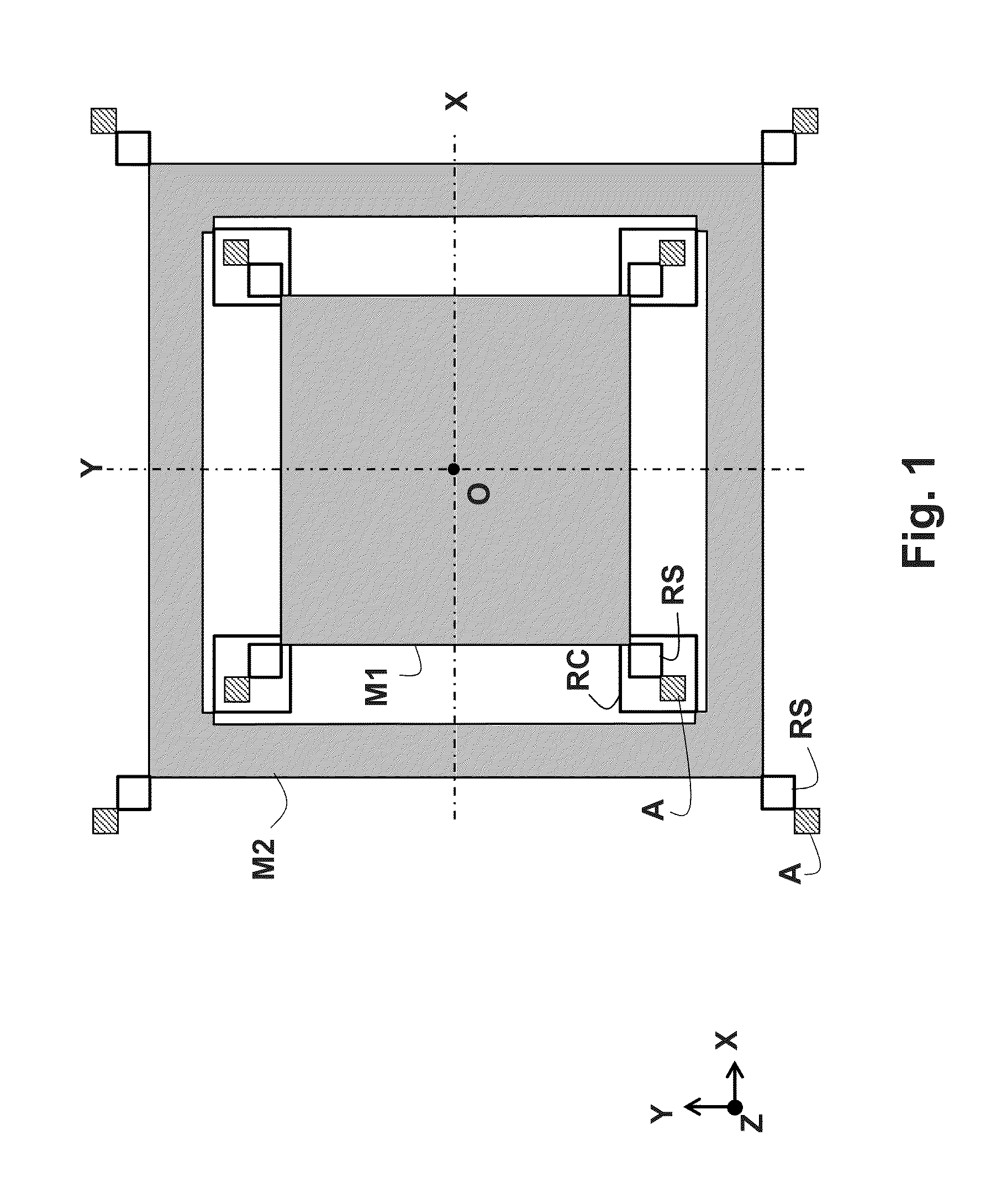
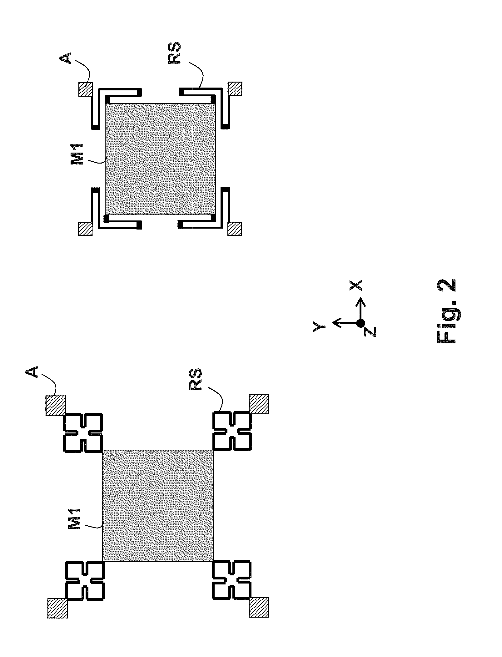
The patent describes a new design for a resonant system that reduces vibration modes and allows for better separation of useful vibration modes. The structure is made using a single layer of silicon, which reduces imperfections and defects. The design also includes at least one electrostatic transducer for compensating a positive or negative quadrature bias, which aligns the principal axes of dynamic stiffness with the axes of symmetry. The mobile assemblies in the structure have a symmetrical distribution of masses and stiffnesses, which reduces sensitivity to disturbances that may cause static de-positioning of the mobile masses. Overall, the design offers improved performance and stability of the resonant system.

Problems solved by technology

The performance of such sensors may be degraded by the energy losses of the resonators to the exterior.
However, energy losses persist in such sensors, since the secondary resonator is not balanced by construction.
Therefore, this mode transmits a torque to the support of the tuning fork, thereby rendering this mode sensitive to the conditions of fixing to the support and to the exterior disturbances transmitted by the support.
In these various structures, residual imperfections of balancing of the resonators persist, as well as parasitic couplings between the excitation mode and the detection mode, which may be due to the imbalances of the various elastic suspension and coupling means used.

Method used


Image

  • MEMS angular inertial sensor operating in tuning fork mode
  • MEMS angular inertial sensor operating in tuning fork mode
  • MEMS angular inertial sensor operating in tuning fork mode

Examples


Embodiment Construction

[0068]The principles of fabrication of an MEMS inertial sensor are firstly briefly recalled: a thin silicon wafer is machined to make a gyrometer whose sensitive axis Z is perpendicular to the plane XY of the wafer and whose excitation and detection motions are situated in the plane of the wafer.

[0069]Silicon is chosen as preferential material, on the one hand for its mechanical properties and on the other hand for its high conductivity when it is sufficiently doped with an appropriate impurity (boron in general for silicon of type P). The conducting silicon makes it possible to carry out the electrical functions of the sensor, notably the electromechanical transduction functions which are generally carried out by electrodes as interdigitated capacitive combs energized with electrical current or voltage; the teeth of these combs, machined directly in the conducting silicon, serve as plate of capacitors useful for the excitation functions and for the detection functions.

[0070]The thi...


PUM


Abstract

A vibrating inertial sensor is provided, micro machined in a plane thin wafer, allowing the measurement of an angular position or of an angular speed. The sensor comprises two vibrating masses suspended by springs with identical stiffness in X and Y and coupled together by identical stiffness springs in X and Y, and at least excitation transducers and detection transducers disposed on at least one of the masses. The mobile assembly consisting of a vibrating mass and the parts of transducers fastened to this mass has a generally symmetric structure with respect to an axis of symmetry OX and with respect to an axis of symmetry OY.

Description

CROSS-REFERENCE TO RELATED APPLICATION[0001]This application claims priority to foreign French patent application No. FR 1401451, filed on Jun. 27, 2014, the disclosure of which is incorporated by reference in its entirety.FIELD OF THE INVENTION[0002]The invention relates to a vibrating inertial sensor, micro-machined in a plane thin wafer, allowing the measurement of an angular position (gyroscope) or of an angular speed (gyrometer).BACKGROUND[0003]The fabrication of these micro-machined sensors, also called MEMS (Micro-Electro-Mechanical-Systems) sensors, uses techniques of collective micro-machining, etching, doping depositions, etc., similar to those which are used for the fabrication of electronic integrated circuits, allowing low production costs.[0004]Such MEMS inertial sensors produced on a silicon or quartz wafer by micro-machining are already known. The structure is planar, in the plane of the silicon or quartz substrate in which it is etched.[0005]These sensors consist of...

Claims


Application Information

Patent Timeline
IPC IPC(8): G01C19/5621
CPCG01C19/5747G01C19/574
Inventor CHAUMET, BERNARDFILHOL, FABIENROUGEOT, CLAUDELEVERRIER, BERTRAND
Owner THALES SA
Learn More