
Radiation image processing device, radiation image processing method and program

a radiation image and processing device technology, applied in the field of radiation image processing devices and radiation image processing methods and programs, can solve the problems of reducing the contrast of the acquired radiation image, difficult to view images, and a large burden on the patient at the time of imaging,

Active Publication Date: 2015-12-31
FUJIFILM CORP
View PDF1 Cites 26 Cited by
  • Summary
  • Abstract
  • Description
  • Claims
  • Application Information

AI Technical Summary

Benefits of technology

The invention relates to a method for improving the quality of radiation images by eliminating scattered radiation using a virtual grid. By acquiring the virtual grid characteristic and performing the scattered radiation elimination processing based on it, the method provides the same effect of a practical scattered radiation elimination grid, resulting in image quality close to that of various types of scattered radiation elimination grids. Additionally, the invention also includes a method for acquiring scattered component information and performing scattered radiation component processing based on it, providing a more precise effect of scattered radiation elimination.

Problems solved by technology

In the related art, when imaging a radiation image of a subject with radiation transmitted through the subject, if the thickness of the subject is particularly great, there is a problem in that radiation is scattered inside the subject, and contrast of the acquired radiation image is degraded due to scattered radiation.
If imaging using a grid is performed, a thin stripe pattern (moire) corresponding to the grid is included in the radiation image along with a subject image, and thus, an image is hard to view.
For this reason, the burden of work to dispose the grid and the burden of the patient at the time of imaging are great.
In the case of a convergence type grid, concentration unevenness may occur in the radiation image due to oblique incidence of radiation.
A fine stripe pattern (more) corresponding to the pitch of the grid is recorded in the radiation image along with a subject image, and the radiation image may be hard to view.

Method used


Image

  • Radiation image processing device, radiation image processing method and program
  • Radiation image processing device, radiation image processing method and program
  • Radiation image processing device, radiation image processing method and program

Examples


first embodiment

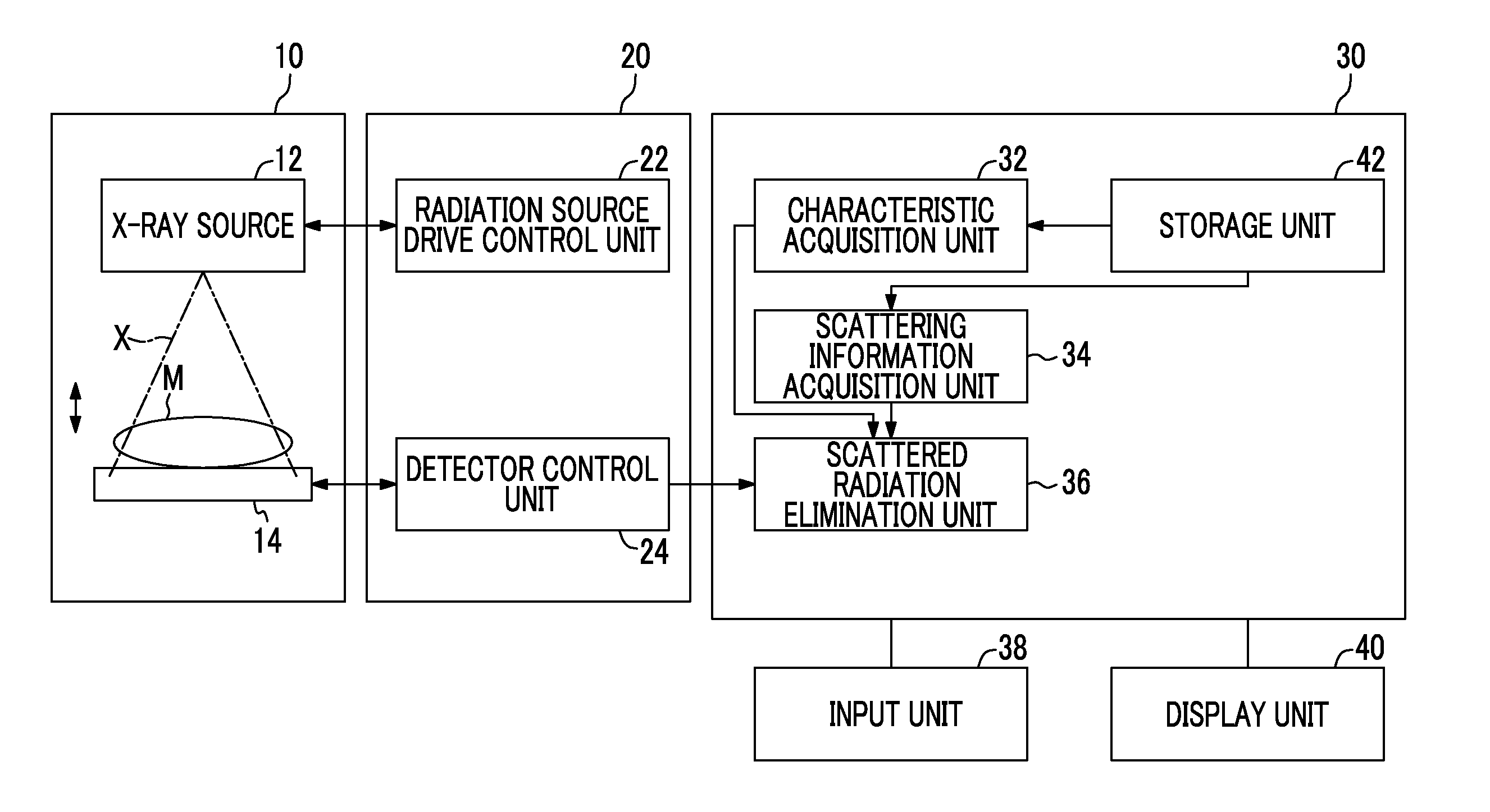
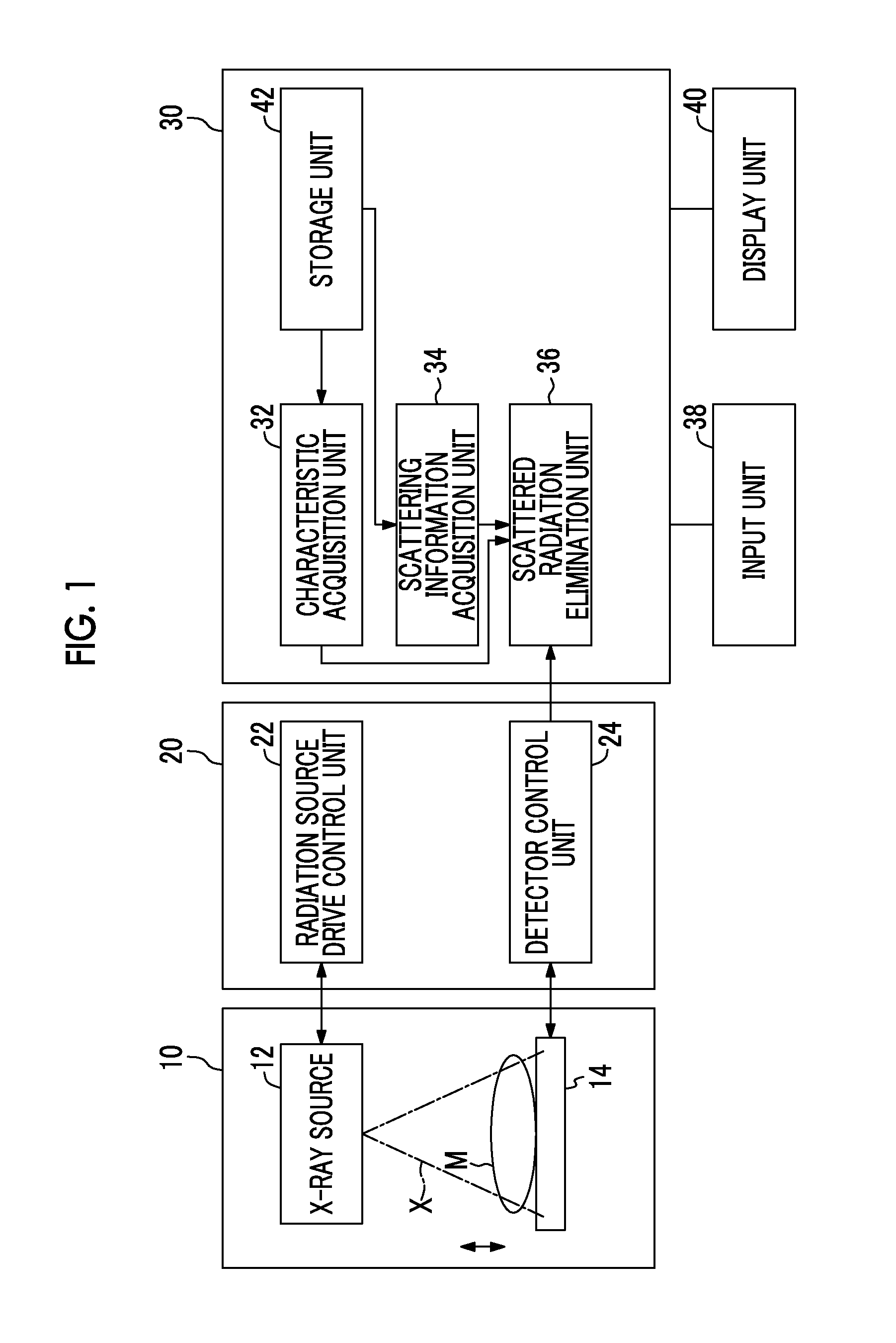
[0038]Hereinafter, an embodiment of the invention will be described referring to the drawings. FIG. 1 is a schematic block diagram showing the configuration of a radiation imaging system to which a radiation image processing device according to the invention is applied. As shown in FIG. 1, the radiation imaging system of this embodiment includes an imaging device 10, a control device 20 which controls the system, and a radiation image processing device 30.

[0039]The imaging device 10 includes an X-ray source 12 which irradiates a subject M with X-rays x, and a radiation detector 14 which detects X-rays transmitted through the subject M to acquire a radiation image of the subject M. In this embodiment, a scattered radiation elimination grid which eliminates scattered radiation scattered by the subject M among the X-rays x transmitted through the subject M is not disposed between the subject M and the radiation detector 14.

[0040]The control device 20 includes a radiation source drive c...

second embodiment

[0086]In the second embodiment described above, the scattered radiation elimination unit 36 may eliminate scattered radiation of the radiation image as follows. First, similarly as above, if frequency resolution is represented by I(x,y)=ΣrI(x,y,r), the frequency component image I(x,y,r) is resolved into a scattered radiation component Is(x,y,r) and a primary radiation component Ip(x,y,r) using the scattered radiation content distribution S(x,y) by Expression (7) described above. Image conversion is performed by applying the scattered radiation transmittance Ts(r) and the primary radiation transmittance Tp(r) as the virtual grid performance respectively to the scattered radiation component Is(x,y,r) and the primary radiation component Ip(x,y,r) by Expression (13) described below, and a scattered radiation elimination component ΔIs(x,y,r) and a primary radiation elimination component ΔIp(x,y,r) are calculated.

ΔIs(x,y,r)=Is(x,y)×(1−Ts(r))=S(x,y)×I(x,y)×(1−Ts(r))

ΔIp(x,y,r)=Ip(x,y)×(1−Tp...


PUM


Abstract

It is possible to allow image processing on a radiation image such that the same effect of scattered radiation elimination as when imaging is actually performed using a grid is obtained. When performing processing for eliminating scattered radiation included in radiation transmitted through a subject M on a radiation image imaged by irradiating the subject M with radiation, a characteristic acquisition unit 32 acquires a virtual grid characteristic as a characteristic of a virtual grid assumed to be used to eliminate scattered radiation at the time of imaging of the radiation image. A scattered radiation elimination unit 36 performs scattered radiation elimination processing of the radiation image based on the virtual grid characteristic.

Description

CROSS REFERENCE TO RELATED APPLICATIONS[0001]This application is a Continuation of PCT International Application No. PCT / JP2014 / 055851 filed on Mar. 6, 2014, which claims priority under 35 U.S.C §119(a) to Japanese Patent Application No. 2013-067794 filed on Mar. 28, 2013, and to Japanese Patent Application No. 2013-229940 filed on Nov. 6, 2013, all of which are hereby expressly incorporated by reference into the present application.BACKGROUND OF THE INVENTION[0002]1. Field of the Invention[0003]The present invention relates to a radiation image processing device and a radiation image processing method which perform image processing on a radiation image, and a program which causes a computer to execute the radiation image processing method.[0004]2. Description of the Related Art[0005]In the related art, when imaging a radiation image of a subject with radiation transmitted through the subject, if the thickness of the subject is particularly great, there is a problem in that radiatio...

Claims


Application Information

Patent Timeline
IPC IPC(8): G06T7/00G06T5/10A61B6/00
CPCA61B6/5282G06T5/002G06T5/10G06T2207/10116G06T7/0012G06T2207/20048G06T2207/20224G06T2210/41G06T2207/20016G06T2207/30004G06K9/4604G06T2207/20221G06T5/50G06T2207/30061G06T5/70
Inventor IMAI, YOSHIRO
Owner FUJIFILM CORP
Learn More