Video display appliance including device for eliminating radiation wave

A cathode ray tube, video display technology, applied in the direction of cathode ray tube/electron beam tube, electrode device and related components, eliminating unnecessary electromagnetic effects, etc. Mass production, etc.

Inactive Publication Date: 2003-02-26
LG ELECTRONICS INC
View PDF3 Cites 0 Cited by
  • Summary
  • Abstract
  • Description
  • Claims
  • Application Information

AI Technical Summary

Problems solved by technology

However, such panels require expensive special processing and are difficult to mass produce
Due to this shielding plate, the transmission performance of the CRT monitor is reduced, so the brightness of the monitor

Method used


Image

  • Video display appliance including device for eliminating radiation wave
  • Video display appliance including device for eliminating radiation wave
  • Video display appliance including device for eliminating radiation wave

Examples


Embodiment Construction

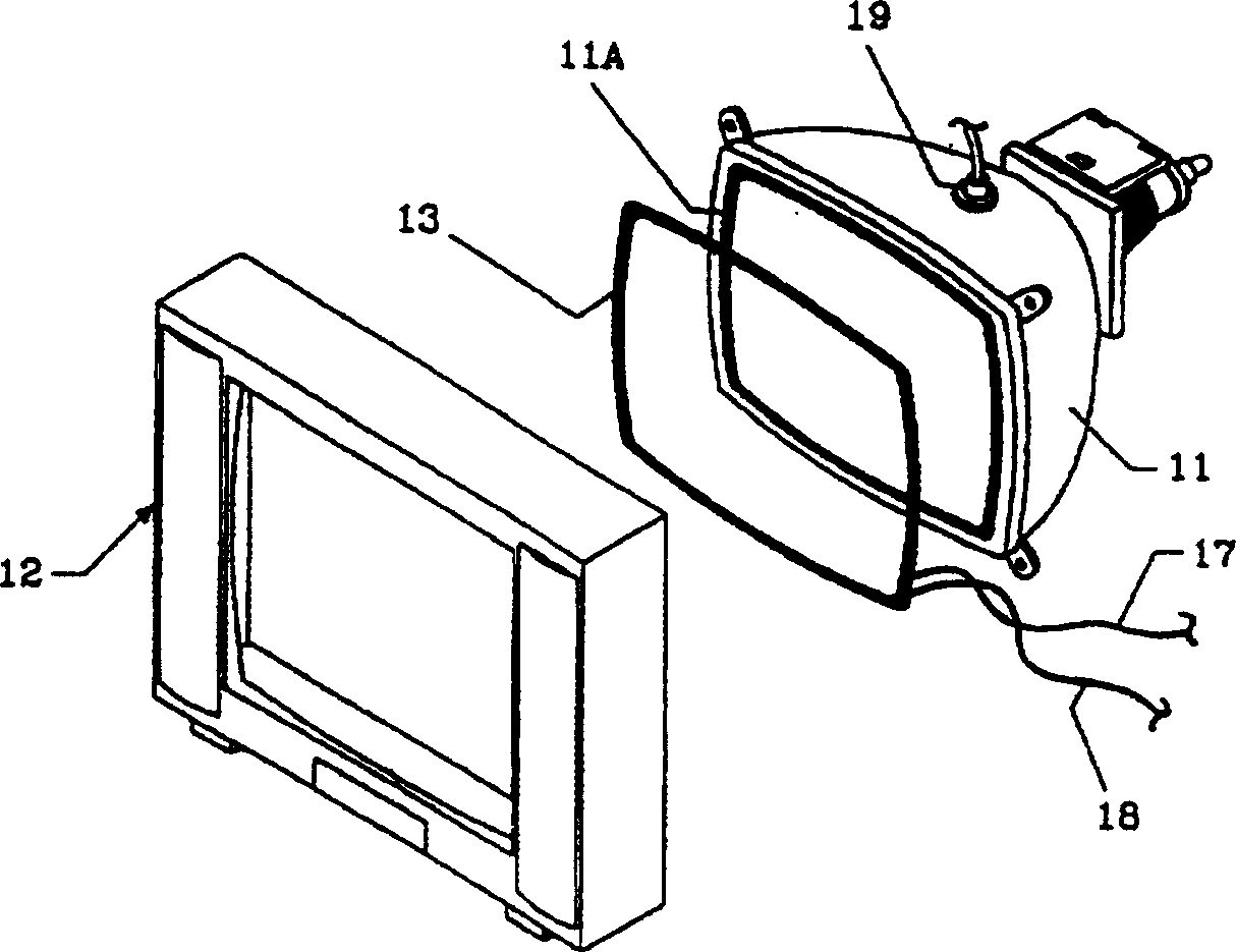
[0023] figure 2 A CRT 11 is illustrated for displaying images by applying the high voltage of a flyback transformer to its anode 19 . The CRT 11 has a phosphor screen frame 11A on the periphery of its screen, on which a composite coil 13 is mounted. The composite coil 13 is sandwiched between a recessed portion 12C (for Figure 4 As shown), the concave portion 12C is formed between a protrusion 12A and a guide rail 12B located on one side of the housing and connected to the CRT 11 .

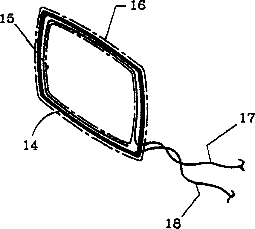
[0024] Composite coil 13 such as image 3 What is shown in detail includes a demagnetization coil 14 and a shielded wire 15 wound one or more times around the periphery of the demagnetization coil in an open loop form. The degaussing coil 14 and the shielding wire 15 are surrounded by a coating 16 to achieve the purpose of isolation from the outside world. Lead wires 17, 18 are connected to the degaussing coil 14 and the shield wire 15, and the negative voltage pulse induced in the third wind...


PUM


Abstract

A video display appliance having a device for eliminating the radiation wave emitted from a cathode ray tube. The appliance includes a shielding wire wound one to several times along the periphery of a degaussing coil. The pulses having the same level and phase, but inverse polarity to those applied to an anode of the cathode ray tube, is applied to the shielding wire, thereby offsetting the radiation wave emitted from the cathode ray tube.

Description

technical field [0001] This invention relates to video display devices, such as television receivers, computer monitors, etc., and more particularly to video display devices including means for canceling the electric fields emitted by cathode ray tubes. Background technique [0002] Commonly used video display devices include a cathode ray tube (CRT), a cabinet, and a back cover. The case and back cover are made of thermoplastic material that is bonded together to house the CRT. The inside of the CRT is a high vacuum and includes a funnel-shaped bulb with a screen and a neck, an electron gun mounted on the neck of the bulb for emitting electron beams, and a deflection device mounted outside the neck. [0003] In a cathode ray tube such as the one described above, the electron beams emitted from the cathodes of the electron guns are controlled and accelerated by conventional means so as to strike the phosphors located on the back of the screen. In this process, the horizont...

Claims


Application Information

Patent Timeline
IPC IPC(8): H01J29/76H01J29/00H04N3/185
CPCH01J2229/0023H04N3/185H01J29/003H01J29/867H01J2229/0053H01J2229/8636
Inventor 郑锡和
Owner LG ELECTRONICS INC
Why Eureka
Try Eureka