
Apparatus for the generation of low-energy x-rays

Inactive Publication Date: 2016-01-07
ENXRAY
View PDF24 Cites 2 Cited by
  • Summary
  • Abstract
  • Description
  • Claims
  • Application Information

AI Technical Summary

Benefits of technology

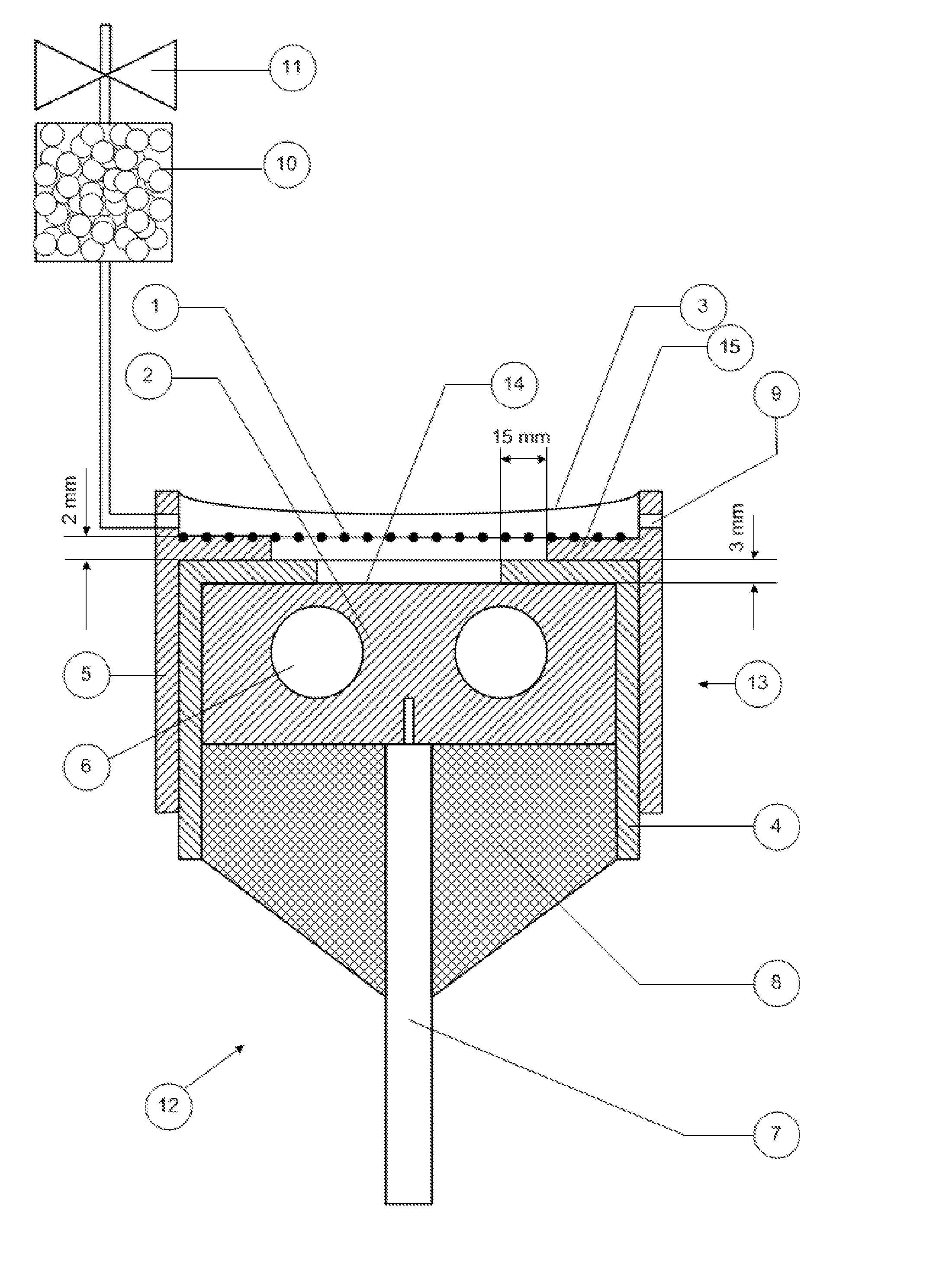
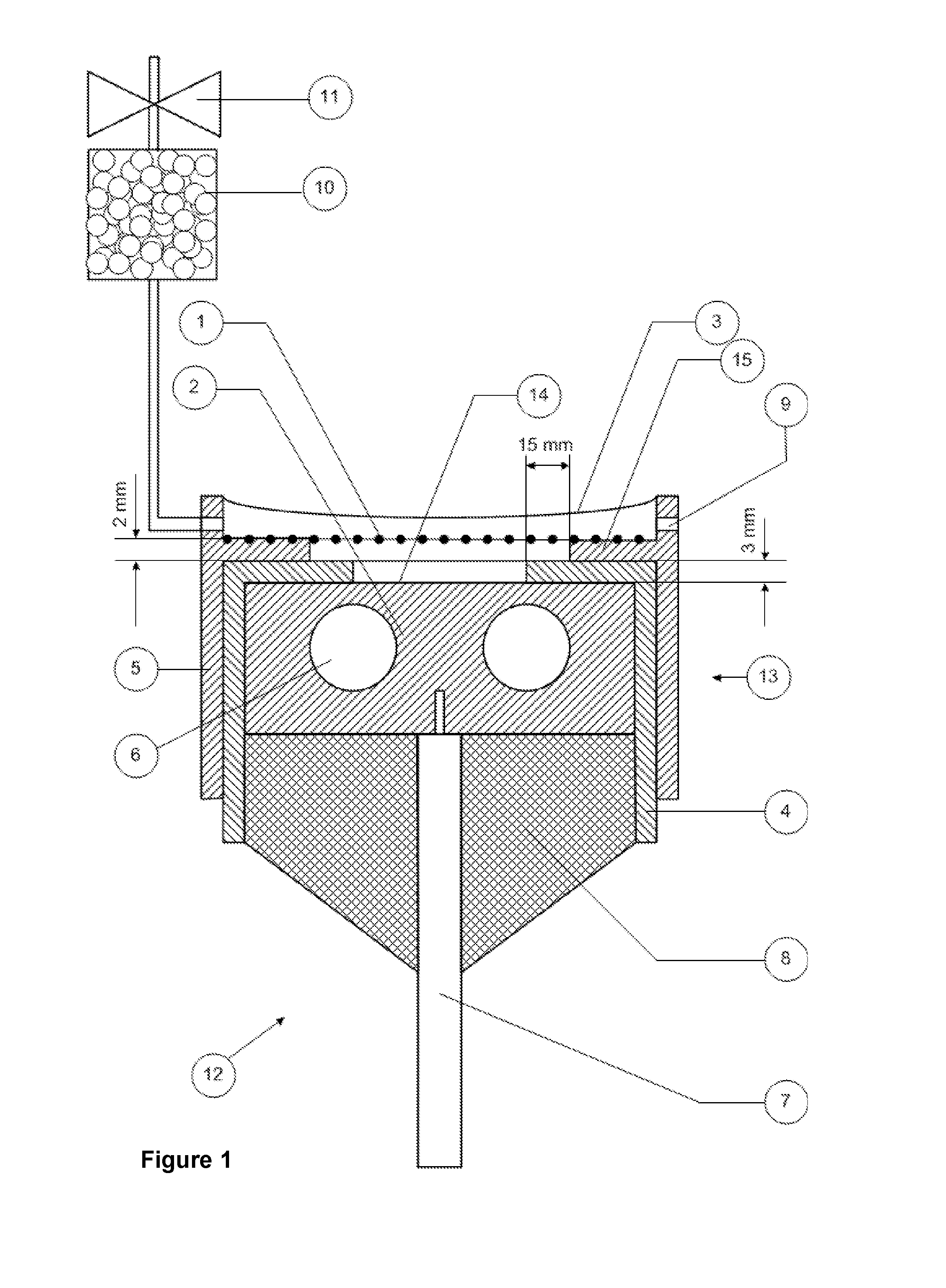
The patent is for an X-ray generating system that has a cathode and an anode with a spacer in between them. This spacer prevents damage to the system caused by electric breakdown between the electrodes. The system also has a window through which X-rays are generated, which is protected from damage by the electric field. The system uses inductive energy storage to generate voltage, which reduces voltage applied to any spark that may be created within the system. The technical effects of this system include increased operational lifetime, consistent operation at elevated power levels, improved stability, reliability and reproducibility, and more homogeneous discharge over a large cross-section of the X-ray emitter head.

Problems solved by technology

Such a dosage requires exposure of the packaging to a radioactive source for a prolonged period of time, usually several hours.
However, vacuum-based X-ray tubes with heated cathodes are not well suited for long periods of heavy duty operation, as would be the case with sterilisation applications.
Existing “soft” X-ray generator systems, such as the one disclosed in GB 2444310 A, suffer from a number of disadvantages, at least in part resulting from the arrangement of the cathode and anode electrodes and the occurrence of arcing between them.
Arcing between the electrodes, and the consequent erosion of the electrodes, leads to a decrease in the operational lifetime of the system.

Method used


Image

  • Apparatus for the generation of low-energy x-rays
  • Apparatus for the generation of low-energy x-rays
  • Apparatus for the generation of low-energy x-rays

Examples


Embodiment Construction

[0052]The present embodiments represent the best ways known to the applicants of putting the invention into practice. However, they are not the only ways in which this can be achieved.

Overview of Presently-Preferred Embodiment

[0053]FIG. 1 illustrates an X-ray generator 12 comprising a gas-filled flash X-ray tube with inductive energy storage for the sterilisation of products such as plastic medical articles. The emitter head 13 of the X-ray tube comprises a cold cathode 1 made of a highly transparent metal grid or mesh, and an anode 2 made of massive metal energized by high-voltage short-duration pulses. Electrons emitted by the grid cathode 1 strike the metal anode 2 and generate characteristic and bremsstrahlung X-ray radiation from the emission surface 14 of the anode 2. The X-ray radiation passes through the cathode grid 1 and irradiates the article(s) to be sterilised.

[0054]An electrically insulating (preferably ceramic) spacer 4 provides means to avoid shorting or arcing of th...


PUM


Abstract

An X-ray source for producing soft X-rays, the X-ray source comprising: a cathode having an electron-emitting structure supported by a support structure, the electron-emitting structure being at least partially transparent to X-rays within a region bounded by the support structure; an anode having an X-ray emitting surface parallel to the electron-emitting structure of the cathode; and an electrically insulating spacer arranged between the anode and the cathode; wherein the electron-emitting structure of the cathode and the X-ray emitting surface of the anode are arranged such that, in use, the electron-emitting structure is operable to bombard the anode with electrons, causing X-rays to be emitted from the X-ray emitting surface and to pass through the cathode; and wherein the insulating spacer is arranged between the anode and the support structure of the cathode and projects beyond the support structure, across part of the anode, into the said region.

Description

FIELD OF THE INVENTION[0001]The present invention relates to apparatus for the generation of X-rays. It is particularly applicable, but by no means limited, to low-energy X-ray generators for sterilising medical articles, pharmaceutical products, or packaging for food or drink products. Other possible applications are discussed below.BACKGROUND TO THE INVENTION[0002]X-ray generators are often used in manufacturing or packaging facilities to sterilise medical articles, pharmaceutical products, or packaging for food or drink products.[0003]In such applications, such as the sterilisation of packaging, conventionally the article to be sterilised is exposed to X-ray radiation produced by means of a radioactive source such as radioactive cobalt. Such radiation comprises “hard” X-rays, i.e. radiation having a high energy, measured in millions of electron volts (eV).[0004]“Hard” X-rays are typically produced by a radioactive decay process, when nuclei undergo a transition into a different e...

Claims


Application Information

Patent Timeline
IPC IPC(8): A61L2/08G01N23/02H01J35/06H01J35/08H01J35/18
CPCA61L2/082H01J35/06H01J35/08H01J2235/18H01J35/18H01J2235/06H01J2235/08G01N23/02H01J35/12H01J35/064
Inventor UDALOV, YURIMITKO, SERGEY
Owner ENXRAY
Learn More