

Method for manufacturing magnetoresistive element
- Summary
- Abstract
- Description
- Claims
- Application Information
AI Technical Summary
Benefits of technology
Problems solved by technology
Method used
Image

Examples
first embodiment
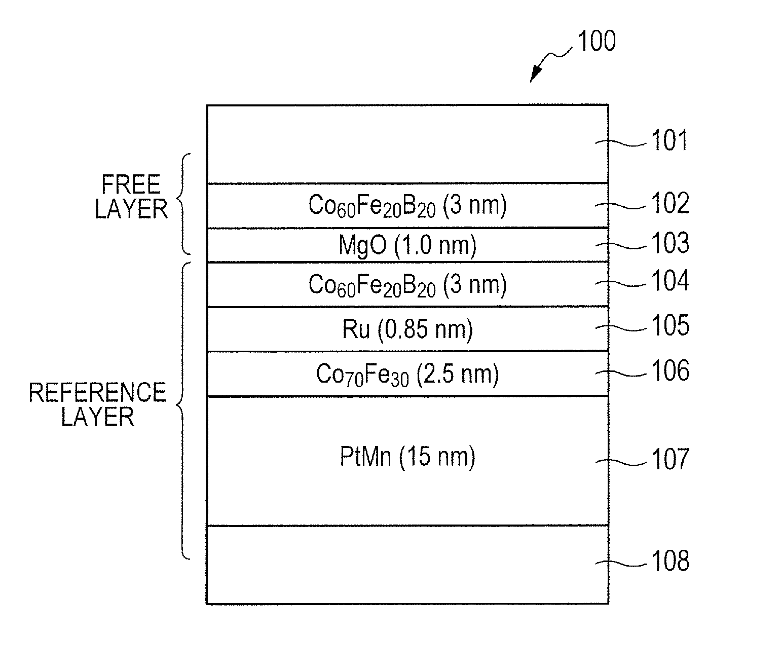
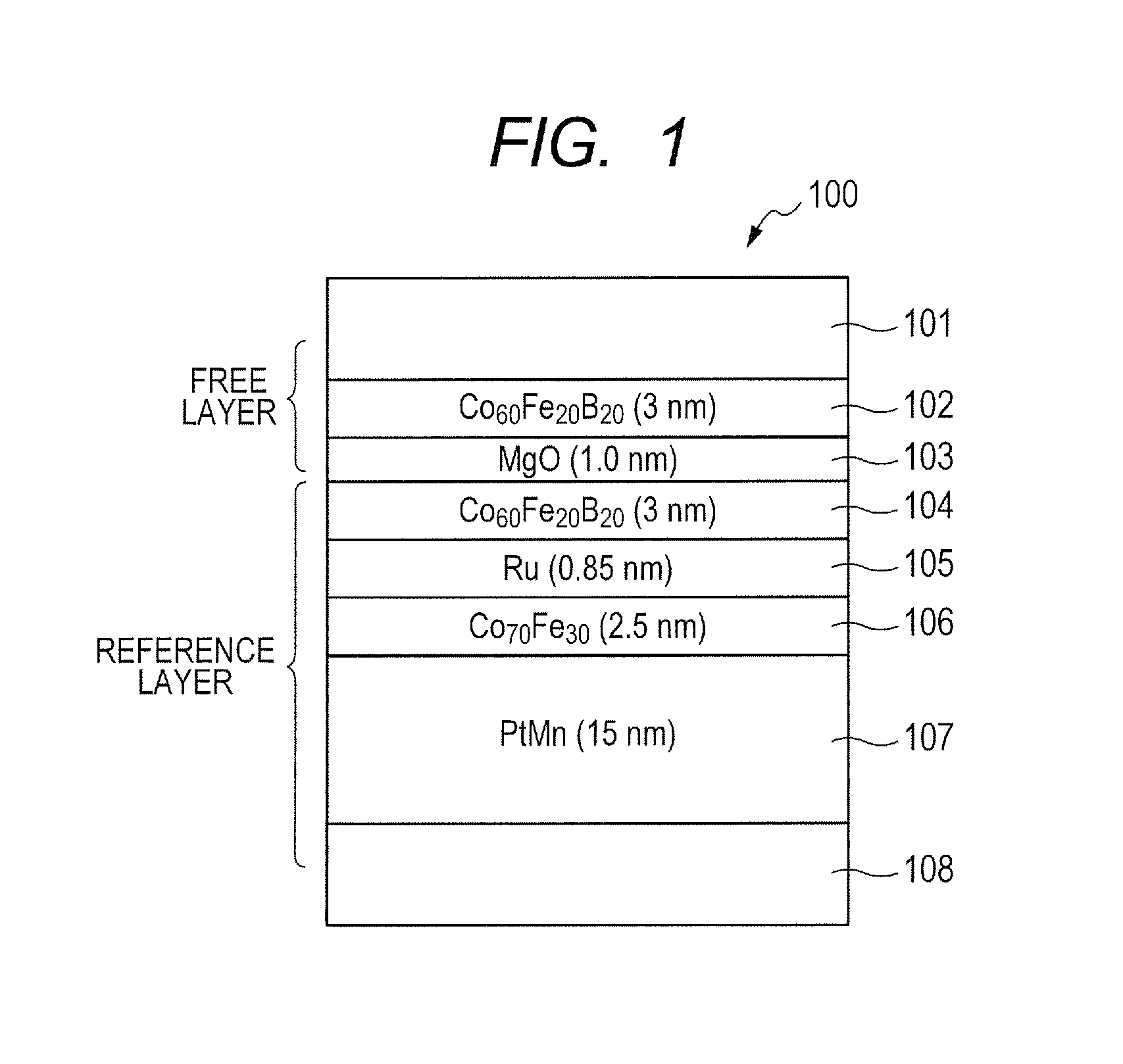
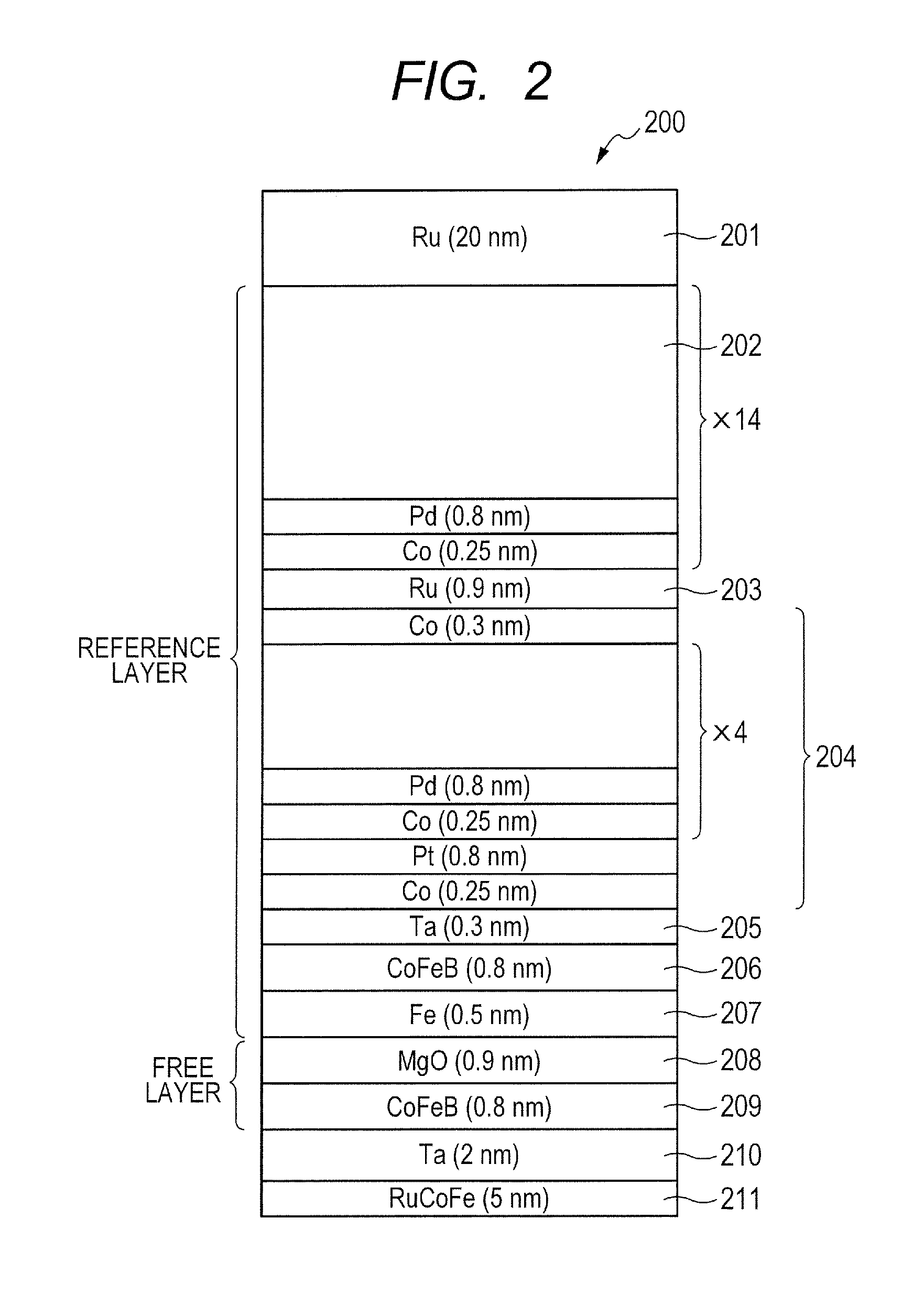
[0043]FIG. 4 is a schematic diagram illustrating a configuration of an oxidation process apparatus 400 according to the embodiment, under a substrate transport condition and under a first oxidation process (or a first oxidation process condition). FIG. 5 is a schematic diagram illustrating the configuration of the oxidation process apparatus 400 according to the embodiment, and illustrates another example of the first oxidation process. FIG. 6 is a schematic diagram illustrating the configuration of the oxidation process apparatus 400 according to the embodiment, under a second oxidation process (or a second oxidation process condition). In the embodiment, the oxidation process apparatus 400 forms a barrier layer of each element illustrated by way of example in FIGS. 1 to 3. In the embodiment, the barrier layer is made of MgO, and a substrate having Mg formed thereon is subjected to the oxidation process in the oxidation process apparatus 400 thereby to form MgO.
[0044]In the embodim...
second embodiment
[0080]In the first embodiment, the oxidation process space 410 smaller than the processing container 401 is formed in the processing container 401; however, the oxidation process space 410 may not be formed. FIG. 11 is a schematic diagram illustrating a general configuration of an oxidation process apparatus according to a second embodiment. An oxidation process apparatus 1100 has the same structure as that of the oxidation process apparatus 400 illustrated in FIGS. 4 to 6, except that the oxidation process apparatus 1100 does not include the cylindrical member 405.
[0081]FIG. 12 is a flowchart illustrating a procedure for an oxidation process in a step of forming a tunnel barrier layer according to the second embodiment.
[0082]At step S121, the slit valve of the substrate transport port 407 is opened to transport the substrate 403 having Mg formed thereon into the processing container 401, and the substrate 403 is mounted on the protrusion portion 404c in a protruding state. After co...
PUM
 Abstract
Description
Claims
Application Information