Transparent heat shielding and insulating member, and method for producing the same

a technology of heat shielding and insulating parts, applied in the direction of optical elements, vacuum evaporation coatings, instruments, etc., can solve the problems of inactive olefin-based resin peeling off, inability to protect the infrared reflection film, inability to remove active olefin-based resin, etc., to achieve excellent abrasion resistance and adhesion, excellent heat shielding function

Active Publication Date: 2016-01-14
MAXELL HLDG LTD
View PDF4 Cites 13 Cited by
  • Summary
  • Abstract
  • Description
  • Claims
  • Application Information

AI Technical Summary

Benefits of technology

[0009]In order to solve the above-described problems, the present invention provides a transparent heat shielding and insulating member including a protective layer that has excellent abrasion resistance and adhesion. The transparent heat shielding and insulating member is obtained by forming the protective layer of a particular resin and also interposing a primer layer of a particular resin between the protective layer and an infrared reflecting layer.
[0010]After keen studies on the aforementioned primer layer for solving the above-described problems, the inventors have found that a modified polyolefin resin having an acid group or a hydroxyl group has excellent adhesion to both of the infrared reflecting layer and the protective layer. Thereby, abrasion resistance of the protective layer can be ensured, and increase of normal emittance and thermal transmittance of the transparent heat shielding and insulating member can be suppressed. And thus the present invention is obtained.
[0013]According to the present invention, it is possible to provide a transparent heat shielding and insulating member having a protective layer excellent in abrasion resistance and adhesion, and having excellent heat shielding function and heat insulating function. Further according to the present invention, it is possible to provide a method for producing a transparent heat shielding and insulating member excellent in coating property of a coating liquid for forming a primer layer.

Problems solved by technology

However, since the protective layer is laminated on the reflecting layer via an adhesive layer, if the material or the thickness of the adhesive layer is inappropriate, the adhesive layer may absorb infrared rays, causing degradation of the heat insulation performance of the infrared reflecting film.
Furthermore, when the film is put in a hot and humid state for a long time, an inactive olefin-based resin may peel off from the adhesive layer.
However, since the squeegee stress relief layer is adhered to the surface of the transparent laminated part via an adhesive layer, the adhesive layer may absorb infrared rays so as to degrade the heat insulation performance of the infrared reflecting film if the material or the thickness of the adhesive layer is inappropriate, such as in the case of JP 2013-010341A.
Furthermore, when the film is put in a hot and humid state for a long time, an inactive olefin-based resin may peel off from the adhesive layer.
However, since the thickness of the hard coat layer is set to be in a range of 0.5 to 30 μm, in a case where the hard coat layer is formed of a material that has a greater infrared absorbency, such as an acrylic resin including an ester bond or a urethane bond or the like, infrared ray will be absorbed more by the hard coat layer when the thickness of the hard coat layer is increased, and it may cause deterioration in the heat insulation performance of the sunshine shielding film.
Moreover, the ionizing radiation curable resin experiences greater shrinkage by curing.
Therefore, in a case where the hard coat layer is formed of the ionizing radiation curable resin, when the ionizing radiation curable resin is coated directly on the aluminum vapor deposition layer as an metal layer, the adhesion between the metal layer and the hard coat layer is degraded to cause peeling of the hard coat layer.
However, when the hard coat layer is exposed for a long time to rays including ultraviolet ray, adhesion with the far infrared reflecting layer may deteriorate due to deterioration or the like of the crosslinked resin.

Method used


Image

  • Transparent heat shielding and insulating member, and method for producing the same
  • Transparent heat shielding and insulating member, and method for producing the same

Examples


example 1

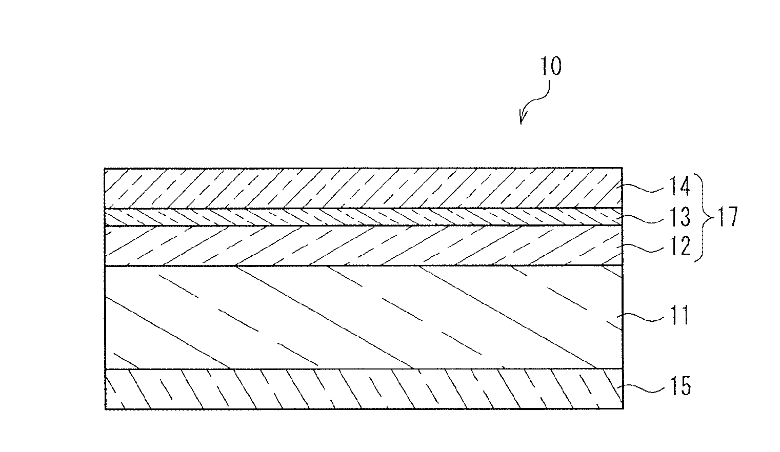
Production of Transparent Base with Infrared Reflecting Layer

[0102]First, as a transparent base, a polyethylene terephthalate (PET) film “A4100” (trade name, thickness: 50 μm) manufactured by TOYOBO CO., LTD. was prepared. The PET film had a surface treated to facilitate adherence. Next, on the surface of the above-described PET film that had been treated to facilitate adherence, a conductive laminated film (infrared reflecting layer) of a three-layered structure of an ITO (indium-tin oxide) layer having a thickness of 30 nm, a silver layer having a thickness of 10 nm, and an ITO layer having a thickness of 30 nm was formed by sputtering, thereby a transparent base with an infrared reflecting layer was produced.

[0103]

[0104]10 parts of modified polyolefin resin solution “HARDLEN NS-2002” (trade name, acid modification type, solid concentration: 20 mass %) manufactured by TOYOBO CO., LTD. was blended with 80 parts of methylcyclohexane and 20 parts of methyl isobutyl ketone as dilution...

example 2

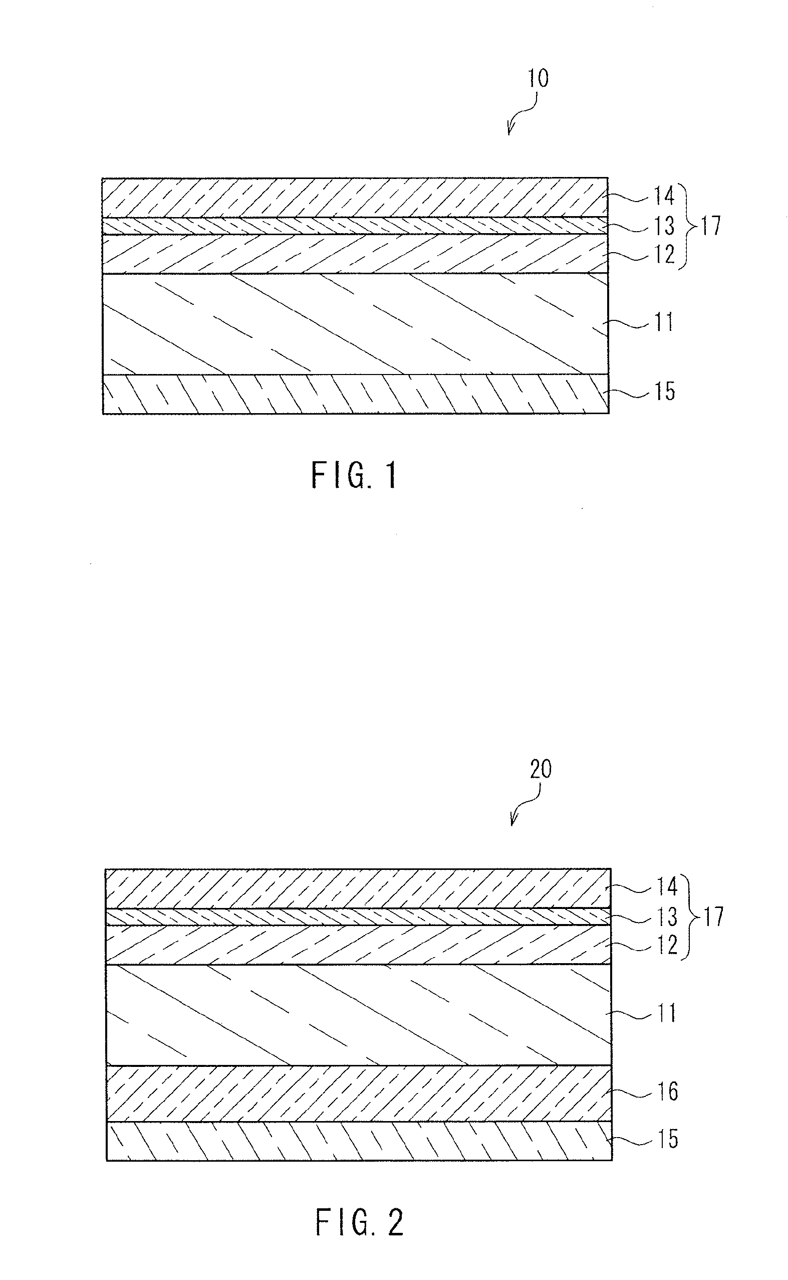
[0113]An infrared reflecting film was produced in the same manner as Example 1 except that the thickness of the protective layer of Example 1 was modified to 2 μm, and the film was stuck to a glass substrate.

example 3

[0114]An infrared reflecting film was produced in the same manner as Example 1 except that the thickness of the protective layer of Example 1 was modified to 0.5 μm, and the film was stuck to a glass substrate.


PUM

PropertyMeasurementUnit
thicknessaaaaaaaaaa
thicknessaaaaaaaaaa
thicknessaaaaaaaaaa

Abstract

A transparent heat shielding and insulating member of the present invention includes a transparent base and a functional layer formed on the transparent base. The functional layer includes an infrared reflecting layer, a primer layer and a protective layer laminated in this order from the transparent base side. The primer layer is formed of a modified polyolefin resin having an acid group or a hydroxyl group, and the protective layer is formed of an ionizing radiation curable resin or a thermosetting resin.

Description

BACKGROUND OF THE INVENTION[0001]1. Field of the Invention[0002]The present invention relates to a transparent heat shielding and insulating member and a method for producing the same.[0003]2. Description of Related Art[0004]From the viewpoint of global warming prevention and energy saving, it has been a trend to shield heat rays of sunshine (infrared ray) that enter through windows of buildings, display windows, windows of automobiles and the like, so as to lower the internal temperatures. Recently, from the viewpoint of energy saving, heat shielding and insulating members have been proposed and have appeared on the market. Such heat shielding and insulating members are provided with not only a heat shielding property for shielding heat rays that will raise internal temperature in the summer, but also a heat insulating function to suppress the leakage of heat from heating equipment indoors in the winter, thereby reducing heating load.[0005]JP 2013-010341A discloses an infrared refl...

Claims


Application Information

Patent Timeline
Patent Type & Authority Applications(United States)
IPC IPC(8): C09D5/00C09D5/33C23C14/08C09D123/26G02B1/14C23C14/34
CPCC09D5/002G02B1/14C23C14/34C23C14/086C09D123/26C09D5/004C09D4/06C09D151/06G02B5/208
Inventor MITSUMOTO, YOSHIMASAOTANI, NORIAKI
Owner MAXELL HLDG LTD
Why Eureka
Try Eureka