Illumination device and projector

a technology of projector and fluorescence, which is applied in the direction of semiconductor devices for light sources, lighting and heating apparatus, instruments, etc., can solve the problems of difficult to achieve the uniformity of fluorescence intensity distribution and fluorescence use efficiency using the optical system, and achieve excellent quality

Active Publication Date: 2016-01-14
SEIKO EPSON CORP
View PDF4 Cites 12 Cited by
  • Summary
  • Abstract
  • Description
  • Claims
  • Application Information

AI Technical Summary

Benefits of technology

[0014]According to the projector according to the second aspect, since the illumination device ac

Problems solved by technology

In the related art as described above, it is difficult to achieve both the use efficiency of the fluorescence and the uniformity of the intensity d

Method used


Image

  • Illumination device and projector
  • Illumination device and projector
  • Illumination device and projector

Examples


first embodiment

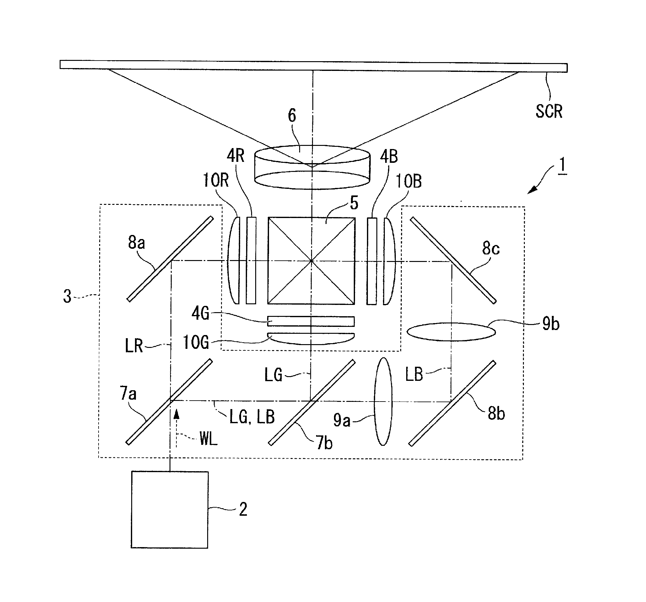
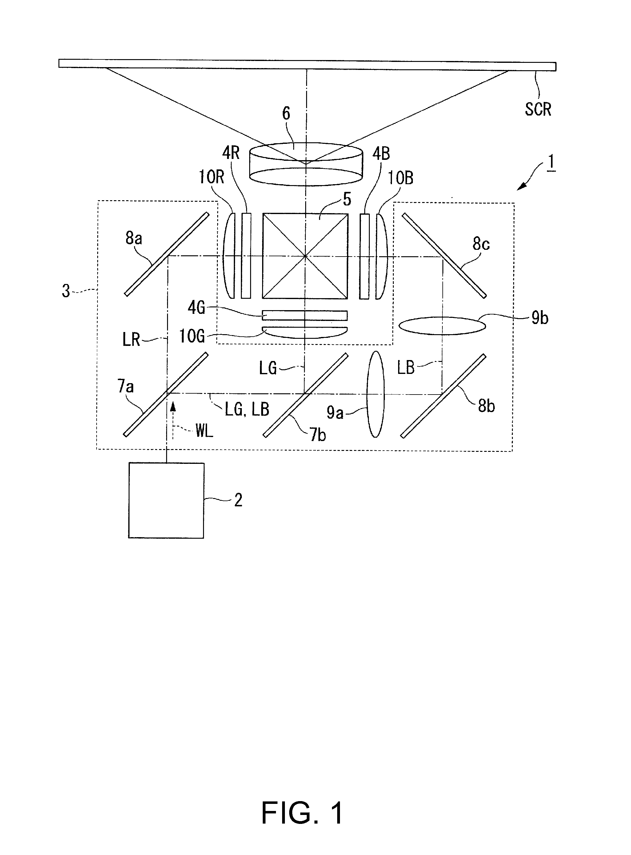
[0023]First, an example of a projector according to a first embodiment will be described. The projector of the embodiment is a projection type image display device that displays a color video (image) on a screen (projected surface) SCR. The projector 1 uses three light modulators corresponding to respective color lights of red light, green light, and blue light. The projector uses, as light sources of an illumination device, semiconductor lasers (laser light sources) with which high-luminance, high-output light is obtainable.

Projector

[0024]FIG. 1 is a plan view showing a schematic configuration of the projector according to the embodiment. As shown in FIG. 1, the projector 1 includes an illumination device 2, a color separation optical system 3, a light modulator 4R, a light modulator 4G, a light modulator 4B, a combining optical system 5, and a projection optical system 6.

[0025]The color separation optical system 3 separates illumination light WL into red light LR, green light LG, ...

second embodiment

[0080]Next, an illumination device 2A shown in FIG. 4 will be described as a second embodiment. FIG. 4 is a plan view showing a schematic configuration of the illumination device 2A.

[0081]The second embodiment differs from the first embodiment in the position at which a chromatic aberration-correcting optical element is disposed, and configurations other than the position are common with those of the first embodiment. Therefore, in the following description, a description of portions equivalent to those of the illumination device 2 shown in FIG. 2 is omitted, and the portions are denoted by the same reference numerals and signs in the drawing.

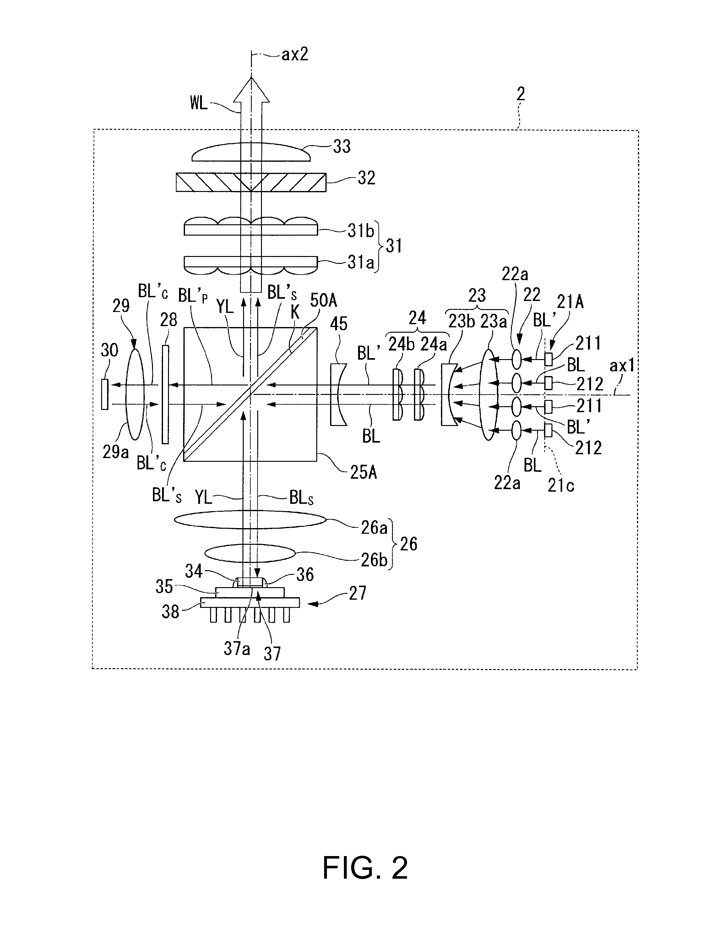
[0082]As shown in FIG. 4, the illumination device 2A of the embodiment includes the array light source 21A, the collimator optical system 22, the afocal optical system 23, the homogenizer optical system 24, the optical element 25A including the polarization separation element 50A, the first pickup optical system 26, the fluorescent light-emitti...


PUM


Abstract

An illumination device includes: a light source that emits first light at a first wavelength; an integrator optical system that the first light enters; a wavelength conversion element that converts the first light transmitting through the integrator optical system into second light at a second wavelength different from the first wavelength; a wavelength separation element provided on an optical path of the first light between the integrator optical system and the wavelength conversion element; a pickup optical system that is provided between the wavelength conversion element and the wavelength separation element and receives the first light and the second light; and a chromatic aberration-correcting optical element provided at least one of between the integrator optical system and the wavelength separation element on the optical path of the first light and at downstream of the wavelength separation element on an optical path of the second light.

Description

BACKGROUND[0001]1. Technical Field[0002]The present invention relates to an illumination device and a projector.[0003]2. Related Art[0004]In recent years, a light source device utilizing a phosphor is used in a projector (for example, refer to JP-A-2012-108486). In the light source device, excitation light is condensed by a condensing lens onto a phosphor layer, and fluorescence from the phosphor layer is collimated by the condensing lens. In the light source device as described above, the condensing lens not only condenses the excitation light but also collimates the fluorescence. That is, the condensing lens acts not only as a condensing optical system but also as a collimating optical system.[0005]In order to utilize the fluorescence with high efficiency in the projector, the parallelism of the fluorescence emitted from the light source device is required to be high. Moreover, in order to increase the uniformity of an intensity distribution of the fluorescence, the uniformity of ...

Claims


Application Information

Patent Timeline
IPC IPC(8): G03B21/20F21K99/00G02B27/14
CPCG03B21/2093F21K9/56G02B27/141G03B21/204
Inventor AKIYAMA, KOICHI
Owner SEIKO EPSON CORP
Why Eureka
Try Eureka