
Methods and apparatus for differential phase-contrast cone-beam CT and hybrid cone-beam ct

a phase-contrast cone and computed tomography technology, applied in tomography, instruments, applications, etc., can solve the problems of limited sensitivity and specificity, sharp decline in the probability of metastasis, and limited positive predictive value of mammography, so as to achieve the effect of increasing spatial resolution

Active Publication Date: 2016-01-28
UNIVERSITY OF ROCHESTER
View PDF3 Cites 23 Cited by
  • Summary
  • Abstract
  • Description
  • Claims
  • Application Information

AI Technical Summary

Benefits of technology

The invention aims to improve image quality without increasing the amount of radiation to the patient. It allows for a higher resolution while maintaining the same level of contrast and noise reduction. Additionally, the invention introduces a more robust and mechanically sound system for rotational-gantry cone beam CT imaging. Finally, it reduces the amount of radiation to the patient for grating-based phase contrast cone beam CT imaging.

Problems solved by technology

In addition, as the diameter of the tumor at detection decreases, the probability of metastasis declines sharply.
Specificity and the positive predictive value of mammography remain limited owing to structure and tissue overlap.
Limited sensitivity and specificity in breast cancer detection of mammography are due to its poor contrast detectability, which is common for all types of projection imaging techniques (projection imaging can only have up to 10% contrast detectability), and mammography initially detects only 65-70% of breast cancers.
The relatively low specificity of mammography leads to biopsy for indeterminate cases despite the disadvantages of added cost and the stress it imposes on patients.
Nearly 80% of the over one million breast biopsies performed annually in the U.S. to evaluate suspicious mammographic findings are benign, burdening patients with excessive anxiety and the healthcare system with tremendous cost.
US is a low spatial resolution study, has severe limitations in visualizing and characterizing calcifications and is highly dependent on operator skill
Although CEBMRI has a high sensitivity for invasive cancers, current techniques may be limited in detecting ductal carcinoma in situ (DCIS).
Though a measure of success has been achieved, DBT is fundamentally limited by its constraints in projection geometry; the tomographic slice is not well defined, which can cause a loss of resolution in the axial direction that affects visualization of subtle features, such as amorphous microcalcifications.

Method used


Image

  • Methods and apparatus for differential phase-contrast cone-beam CT and hybrid cone-beam ct
  • Methods and apparatus for differential phase-contrast cone-beam CT and hybrid cone-beam ct
  • Methods and apparatus for differential phase-contrast cone-beam CT and hybrid cone-beam ct

Examples


Embodiment Construction

[0038]Preferred embodiments of the present invention will be set forth in detail with reference to the drawings, in which like reference numerals refer to like elements or steps throughout.

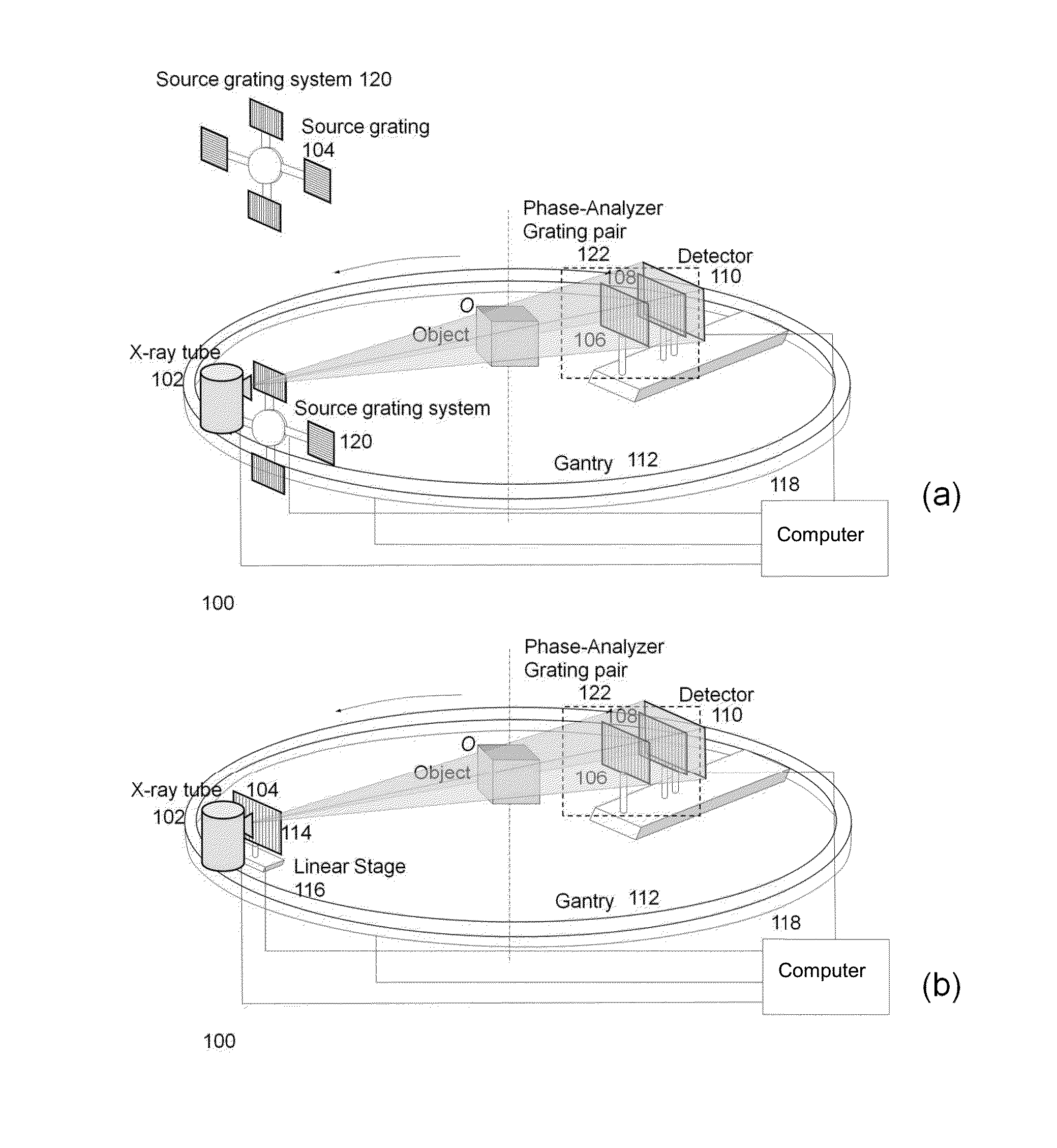
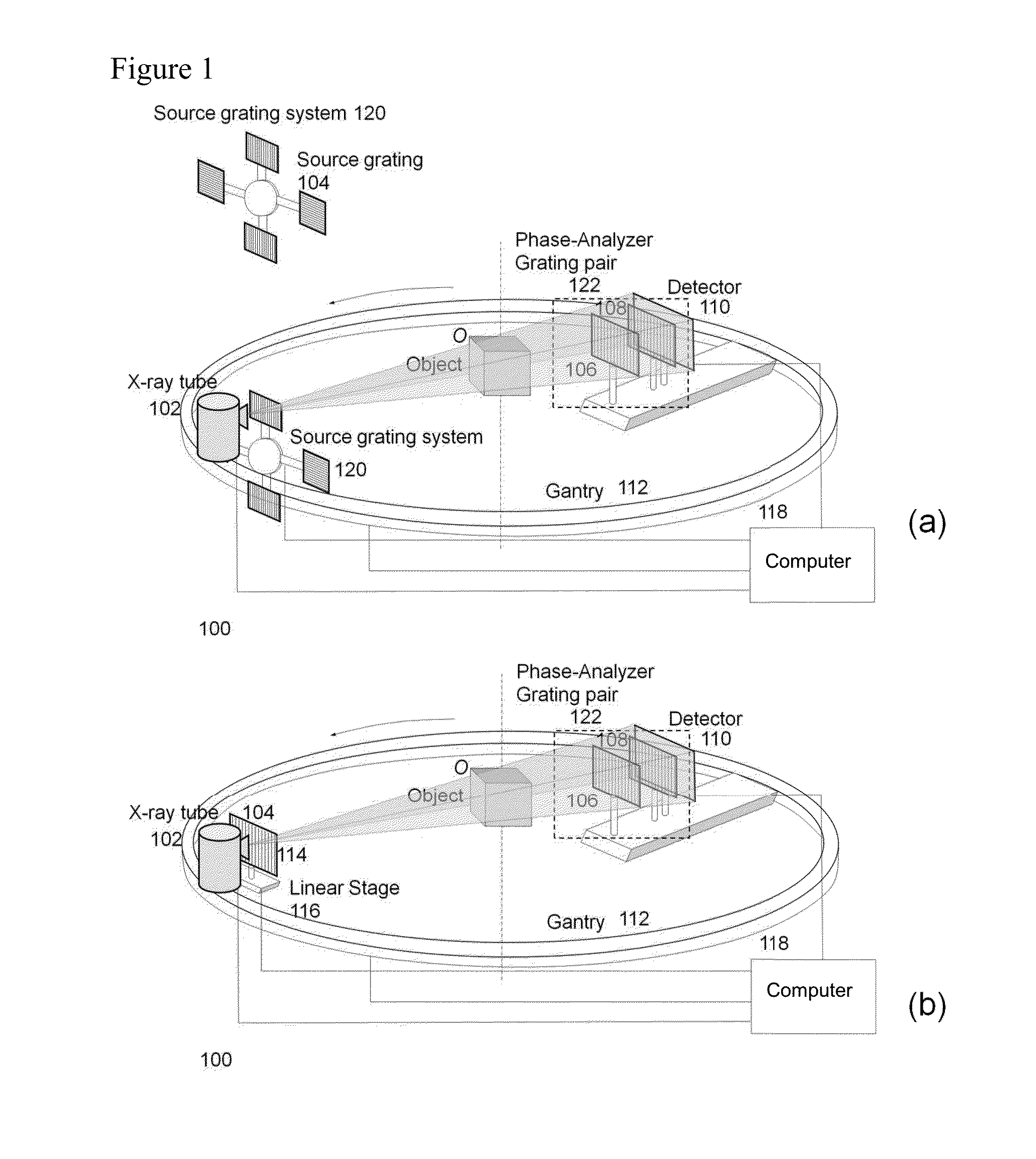
[0039]A first preferred embodiment is directed to a differential phase-contrast cone-beam CT system (DPC-CBCT) for in vivo clinical imaging using the differential phase-contrast imaging technique. As shown in FIGS. 1A and 1B, such a DPC-CBCT system 100 includes a hospital-grade x-ray tube 102 with a source grating 104, a high-resolution detector 110 and a phase-analyzer grating pair 122 mounted on a gantry 112. To ensure the mechanical precision and stability, the source grating will be stepped to improve mechanical tolerance. The stepping mechanism of the source grating can be designed either as the dial source grating system 120 in FIG. 1A or as the linear stage-based mechanism in FIG. 1B. The purpose of the source grating system 120 in FIG. 1A is to produce different phase steps that are define...


PUM


Abstract

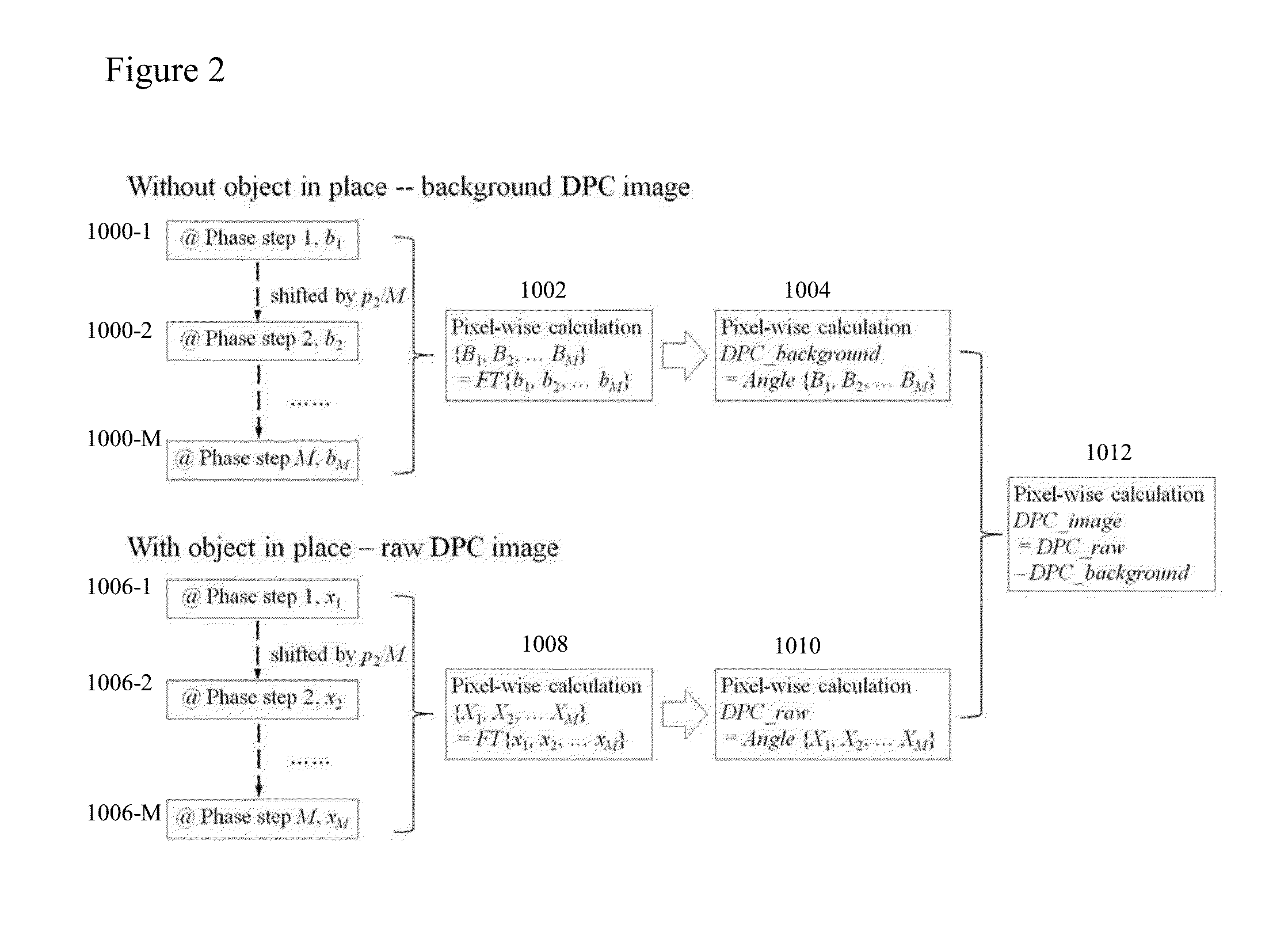
A raw DPC (differential phase contrast) image of an object is acquired. The background phase distribution due to the non-uniformity of the grating system is acquired by the same process without an object in place, and the true DPC image of the object is acquired by subtracting the background phase distribution from the raw DPC image.

Description

REFERENCE TO RELATED APPLICATIONS[0001]The present application claims the benefit of U.S. Provisional Patent Application No. 61 / 606,562, filed Mar. 5, 2012, whose disclosure is hereby incorporated by reference in its entirety into the present disclosure.STATEMENT OF GOVERNMENT INTEREST[0002]This invention was made with government support under Grant No. R01 CA 143050 awarded by National Institutes of Health. The government has certain rights in the invention.FIELD OF THE INVENTION[0003]The present invention is directed to cone-beam computed tomography (CT) imaging and more particularly to phase-contrast cone-beam CT for such uses as breast imaging.DESCRIPTION OF RELATED ART[0004]According to the National Cancer Institute, one out of eight women will be diagnosed with breast cancer in their lifetime. And while a reduction in mortality from breast cancer is evident in published reports, each year 40,000 women will die of the disease.[0005]The optimal breast imaging technique detects t...

Claims


Application Information

Patent Timeline
Patent Type & Authority Applications(United States)
IPC IPC(8): A61B6/00A61B6/03
CPCA61B6/484A61B6/502A61B6/4085A61B6/4291A61B6/466A61B6/03A61B6/032A61B6/4035A61B6/5205G06T11/006
Inventor NING, RUOLACAI, WEIXING
Owner UNIVERSITY OF ROCHESTER
Learn More