Mixed oxide materials

Active Publication Date: 2016-01-28
KONINKLJIJKE PHILIPS NV
View PDF0 Cites 2 Cited by
  • Summary
  • Abstract
  • Description
  • Claims
  • Application Information

AI Technical Summary

Benefits of technology

[0028]Through a combination of two different scintillator materials having a different density, X-rays of different energy levels can be detected, whereby the material of lower density generally detects X-rays of a lower energy, and the material of higher density generally detects X-rays of a

Problems solved by technology

While those two materials already give reasonable results, it has been shown that GOS, due to the fact that it is not transparent to visible light but merely translucent, shows a reasonably high scattering

Method used

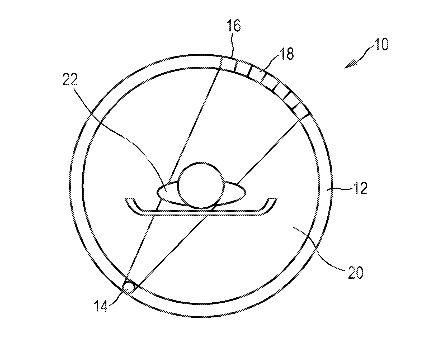
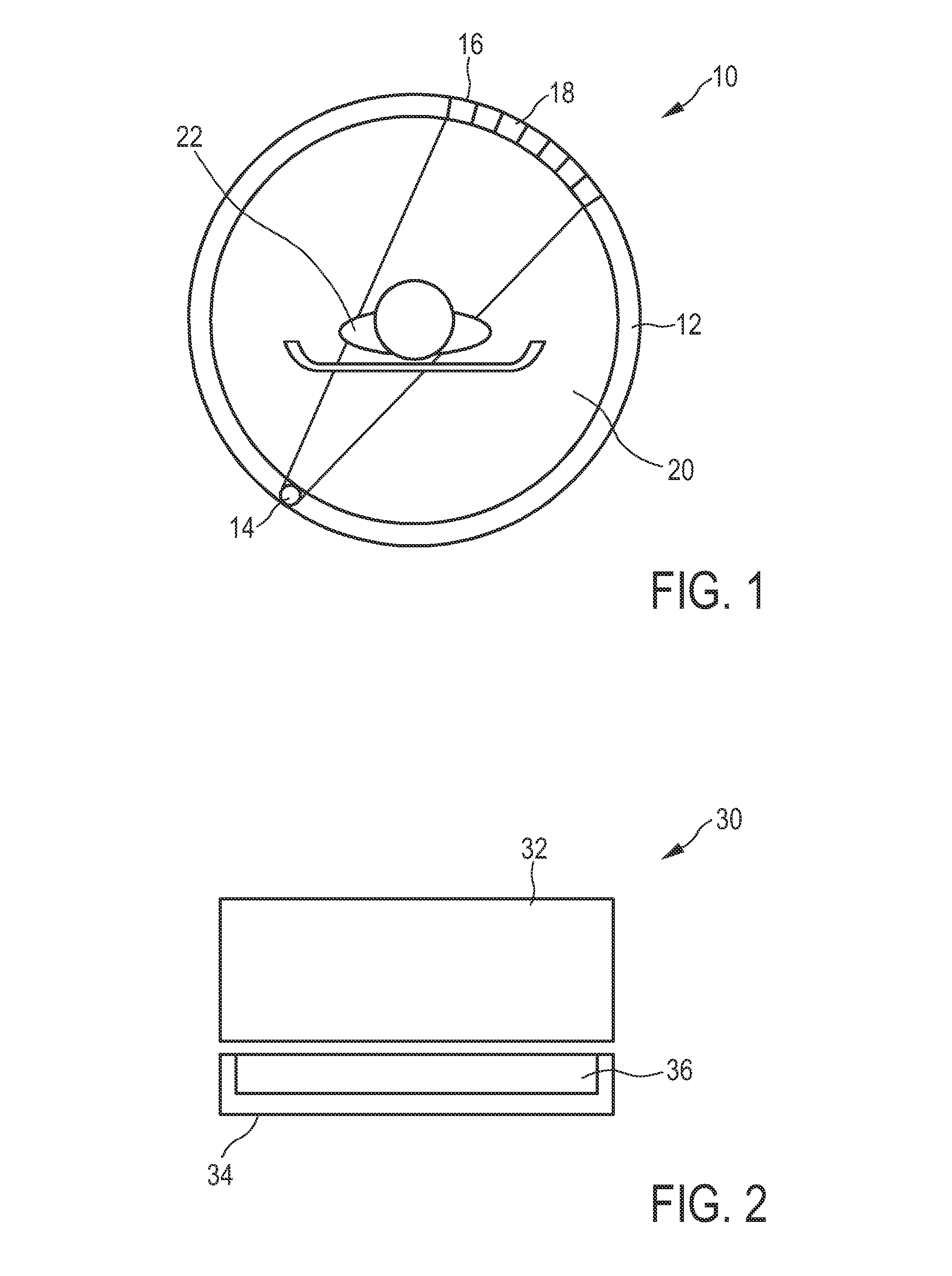
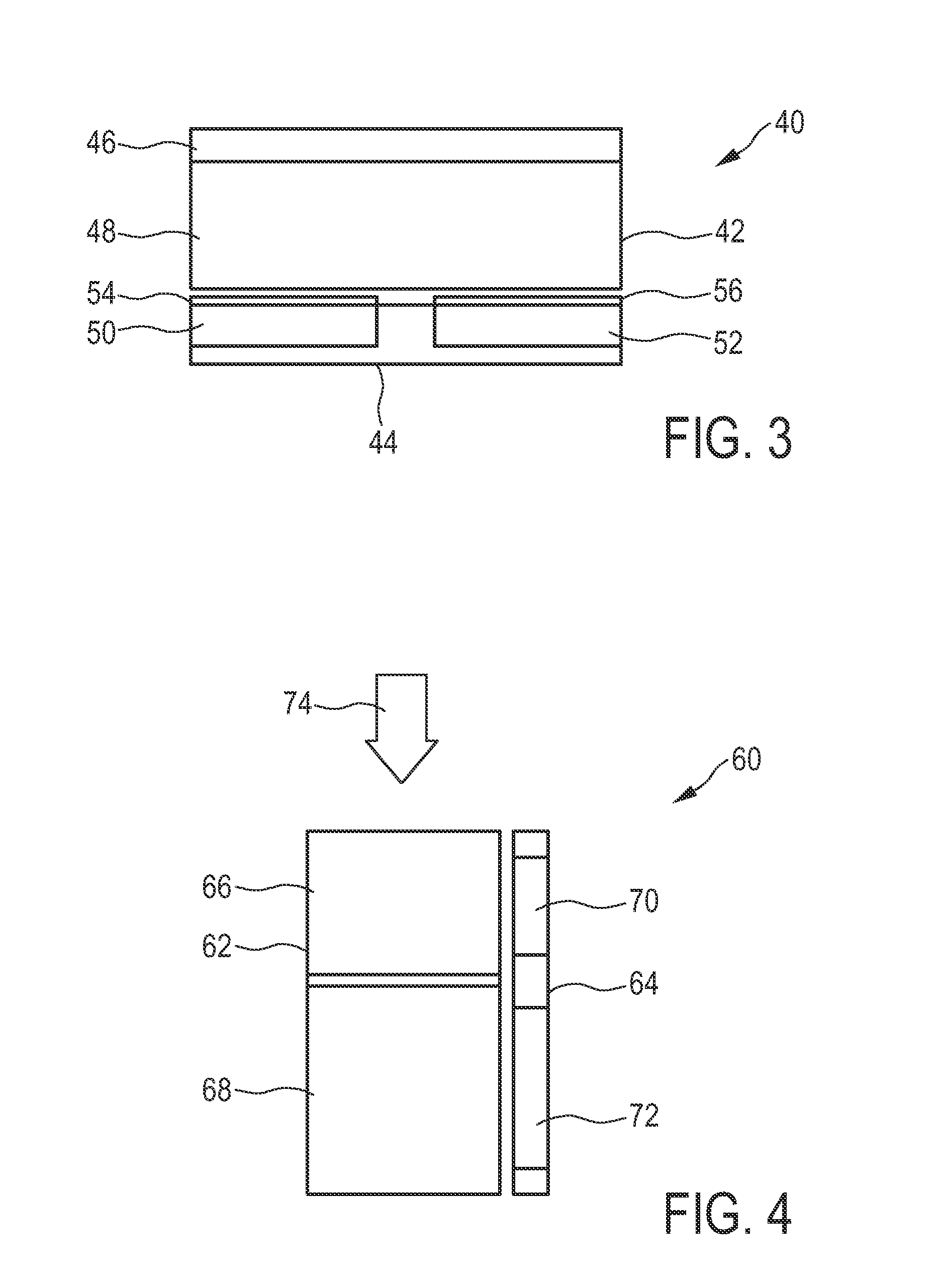

Image

  • Mixed oxide materials
  • Mixed oxide materials
  • Mixed oxide materials

Examples


examples 1 to 4

[0034]Stoichiometric amounts of Y2O3 (Rhodia), CeO2 (Neo Materials), Tb4O7 (Guangdong and Neo Materials), Al2O3 (Baikowski) were weighed in, in proportions to create mixed oxide materials having the formula (Y0.395Tb0.595)3Al5O12:Ce0.01. In order to dope these materials with 25 ppm, 50 ppm, 100 ppm and 200 ppm, respectively of V, a corresponding amount of NH4VO3 was dissolved in ethanol, mixed with the Al2O3, precipitated and dried on a rotary evaporator. The modified Al2O3 obtained this way was then employed in the solid state synthesis of the desired mixed oxides. The solid starting materials were mixed and milled with heptane in agate pots. After the mixing process, the samples were dried in a tube oven to remove the mixing liquid, and the samples were sintered in a horizontal tube furnace (Entech 01820 series) at 1550° C. in an aluminium crucible for 4 hours in a H2 / N2 flow in order to reduce Ce4+ to Ce3+ and Tb4+ to Tb3+.

[0035]The obtained samples were tested for photoluminesce...


PUM


Abstract

The present invention relates to mixed oxide materials, methods for their preparation, detectors for ionizing radiation and CT scanners. In particular, a mixed oxide material is proposed having the formula (Yw Tbx)3Al5-y GayO12:Cez, wherein 0.01≦w≦0.99, 0.01≦x≦0.99, 0≦y≦3.5 and 0.001≦z≦0.10 and wherein w+x+3*z=1, whereby the mixed oxide material is doped with at least 10 ppm V.

Description

FIELD OF THE INVENTION[0001]The present invention relates to mixed oxide materials, methods for their preparation, detectors for ionizing radiation and CT (Computed Tomography) scanners.BACKGROUND OF THE INVENTION[0002]Detectors for ionizing radiation and, in particular, solid state detectors for ionizing radiation are, e.g., widely used in CT scanners. Such solid state detectors for ionizing radiation comprise, broadly speaking, two main subunits. The first subunit comprises a fluorescent component that is usually referred to as a scintillator or a phosphor which absorbs radiation and in response emits photons in the UV, the visible or the IR region.[0003]The second subunit comprises a photodetector which can detect the photons emitted by the scintillator or phosphor and produces corresponding electrical signals.[0004]With regard to the above expressions “scintillator” and “phosphor”, it needs to be noted that both are exchangeable terms and are to be understood within the scope of...

Claims


Application Information

Patent Timeline
IPC IPC(8): C09K11/77A61B6/00A61B6/03G01T1/202
CPCC09K11/7774A61B6/4208A61B6/03G01T1/2023G21K4/00A61B6/032C09K11/62C09K11/69G01T1/2006G01T1/2016
Inventor RONDA, CORNELIS REINDERBOEREKAMP, JACOBUS GERARDUSBUETTNER, DANIELAVAN DONGEN, ANNE-MARIE ANDREEWIECZOREK, HERFRIED KARLSPOOR, SANDRA JOHANNA MARIA PAULADJOHAN, SILVANKEUR, WILHELMUS CORNELIS
Owner KONINKLJIJKE PHILIPS NV
Why Eureka
Try Eureka