Motor Control

a motor control and circuit technology, applied in the direction of torque ripple control, electrical steering, transportation and packaging, etc., can solve the problems of current controller reaction and unwanted acoustic noise, and achieve the effect of reducing the response of the controller

Active Publication Date: 2016-01-28
TRW LIMITED
View PDF6 Cites 15 Cited by
  • Summary
  • Abstract
  • Description
  • Claims
  • Application Information

AI Technical Summary

Benefits of technology

[0012]a noise reduction circuit adapted to identify an operating condition of the system in which the motor is stationary or rotating at a very low speed, and in the event that the operating condition is identified the noise reduction circuit is adapted to reduce the response of the controller to variations in the error signal.
[0013]By reducing the response of the controller to variations in the error signal, such as high frequency variations caused by quantisation errors in the output from a current sensor, the noise reduction circuit may make the controller insensitive to changes in the error signal or reduce the magnitude of any change in the output of the controller in response to a corresponding change in the error signal. In each case, the gain of the controller is effectively reduced when the operating condition in which the motor is stationary or rotating at very low speed.
[0016]Alternatively, the noise reduction circuit may include an attenuator and may be adapted to reduce the sensitivity of the controller to changes in the error signal by attenuating the error signal that is fed to the controller when the certain condition is met. When the error signal is attenuated the magnitude of the noise is reduced, so the reaction of the current controller to the noise is likewise reduced. The current controller will then respond to the attenuated error signal rather than the original, unmodified, signal.
[0017]In a further alternative, the noise reduction circuit may include a filter and may be adapted to reduce the sensitivity of the controller to changes in the error signal by passing the error signal through a filter. This may comprise a low pass filter. The current controller will then respond to the filtered error signal rather than the original, unfiltered, error signal.
[0023]The noise reduction circuit may, instead of using an absolute threshold, apply hysteresis to a signal indicative of motor velocity and compare the signal with hysteresis to the threshold to determine if the condition is met. The use of hysteresis may advantageously stop the noise reduction being switches on and off too rapidly.

Problems solved by technology

This noise will be passed onto the error signal, and if left unchecked will cause the current controller to react because it cannot discriminate between noise and genuine changes in error that should be tracked.
This noise can cause unwanted acoustic noise, especially when the motor is stationary—when it is rotating the quantization noise is disguised as the motor current will be sinusoidally varying.

Method used


Image

  • Motor Control
  • Motor Control
  • Motor Control

Examples


Embodiment Construction

[0049]Referring to FIG. 10 a three phase brushless motor 1 comprises three motor windings 2, 4, 6, generally designated as phases A, B and C. The phases are connected in a star network but could be connected in another arrangement, such as a delta topology. One end of each coil is connected to a respective terminal. The other ends of the coils are connected together to form the star centre 7. The free ends are connected to a switching circuit arranged as an H-bridge.

[0050]The switching circuit comprises a three phase bridge 8, one for each phase of the motor. Each arm 10, 12, 14 of the bridge comprises a pair of switches in the form of a top transistor 16 and a bottom transistor 18 connected in series between a supply rail 20 and ground line 22. The motor windings 2, 4, 6 are each tapped off from between a respective complementary pair of transistors 16, 18.

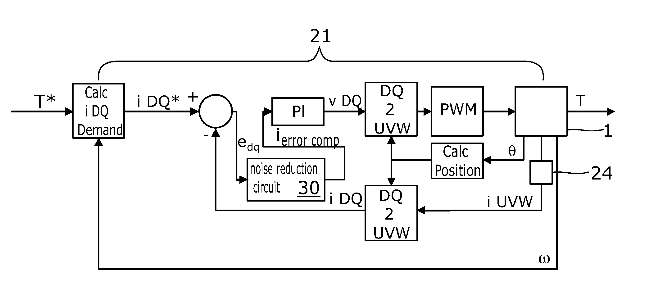
[0051]The transistors 16, 18 are turned on and off in a controlled manner by a motor controller 21, which is shown in detail in...


PUM


Abstract

A motor control circuit for an electric motor of an electric power assisted steering system of the kind in which a measurement of torque carried by a part of the steering system is used to produce a torque demand signal indicative of a torque to be applied to the steering system by the motor, the control circuit comprising a switching circuit comprising a plurality of electrical switches, and a motor current controller that generates voltage demand signals to be passed to a drive circuit for the switches that in turn generates pulse width modulated switching signals for the switching circuit that cause the switches to selectively connect the phases to a power supply so as to cause current to flow through the phases of the motor. The current controller is responsive to an error signal that represents the difference between a current demand signal and an actual current signal, and a noise reduction circuit adapted to identify an operating condition of the system in which the motor is stationary or rotating at a very low speed, and in the event that the operating condition is identified the noise reduction circuit is adapted to reduce the response of the controller to variations in the error signal.

Description

CROSS-REFERENCE TO RELATED APPLICATIONS[0001]This application is a national stage of International Application No. PCT / GB2014 / 050645 filed Mar. 5, 2014, the disclosures of which are incorporated herein by reference in entirety, and which claimed priority to Great Britain Patent Application No. 1304159.5 filed Mar. 7, 2013, the disclosures of which are incorporated herein by reference in entirety.BACKGROUND OF THE INVENTION[0002]This invention relates to improvements in motor control circuits for use in electric power assisted steering systems, and in particular to pulse width modulation (PWM) control of multiple phase brushless motors in electric power assisted steering systems.[0003]Control systems for PWM controlled electric motors, especially DC motors, generally need to measure the current through the windings or phases of the motor and this can either be done by means of separate current sensors for each of the phases, or by means of a single current sensor that is placed in th...

Claims


Application Information

Patent Timeline
Patent Type & Authority Applications(United States)
IPC IPC(8): B62D5/04H02P6/10
CPCH02P6/10B62D5/0487B62D5/0463H02P23/03B62D5/046
Inventor DIXON, CHRISTOPHER, DAVID
Owner TRW LIMITED
Why Eureka
Try Eureka