

Pipe-closing device for isolating a tank, a pipe or a set of tanks and pipes
a technology of pipe-closing device and tank, which is applied in the direction of fluid-tightness measurement, lighting and heating apparatus, instruments, etc., can solve the problems of not being able to achieve perfect leak-tightness, plumbing fixtures are not systematically dimensioned to withstand pressure, and equipped with clamps
Active Publication Date: 2016-02-04
ELECTRICITE DE FRANCE
View PDF11 Cites 5 Cited by
- Summary
- Abstract
- Description
- Claims
- Application Information
AI Technical Summary
Benefits of technology
The invention involves a plug used in piping systems that can be easily handled and positioned at any location in the pipe. The plug has assembly elements that are smaller than the diameter of the main body, allowing for easy movement through small openings. The non-slip pads on the plug ensure a secure holding of the plug, without requiring additional holding mechanisms. This design provides flexibility and ease of use when installing plugs in piping systems.
Problems solved by technology
Nevertheless, plumbing fixtures at the level of each pipe do not in general exist.
Finally, the plumbing technologies generally employed on tanks are often not suited to obtain the perfect leak tightness required for a test or for hydraulic pressure testing, and the plumbing fixtures are not systematically dimensioned to withstand pressurisation during tests or hydraulic pressure testing.
Nevertheless, in industries using so-called hazardous fluids (toxic, inflammable, explosive, etc.) or hot fluids (for example steam), the enclosures and pipeworks are not equipped with clamps which would have made it possible, after dismantling, to install bolted shutters (blind holes, blind clamps), enabling sealing.
Unfortunately, such a technique of sealing pipes has a large number of drawbacks.
Firstly, such a solution implies a complex implementation, generating an intervention of long duration, requiring specific rare human resources (welders, controllers, etc.) and considerable needs in material logistics (gantries, scaffolding, airlock, de-lagging, etc.).
The intervention also comprises risks of important implementation variables (defects, faults, etc.).
Such plugs are robust and make it possible to withstand high pressures but their handling remains very complex, especially when the pipes to seal and isolate have large diameters.
Moreover, the intrinsic leak tightness of such plugs cannot be checked or controlled during leak tightness tests of the duct, which can falsify the results of the test as the case may be.
Nevertheless, the solution proposed is not suitable for large pipe diameters, and cannot withstand the high pressures of leak tightness tests or hydraulic pressure testing.
The structure of such a plug is moreover complex and massive, making its putting in place and implementation more difficult.
Moreover, all existing sealing solutions have the drawback of requiring cutting the pipe which has to be sealed to isolate the tank and thereby form the confined space necessary for the test.
Method used
View moreImage
Smart ImageViewing Examples

Examples
first embodiment
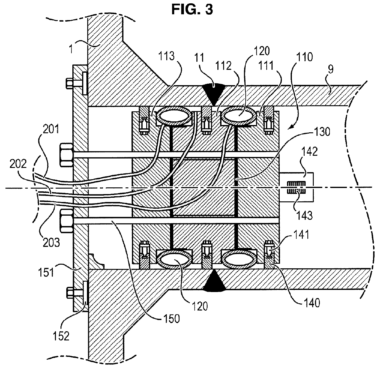
[0042]FIG. 3 is a sectional view of the plug according to the invention placed inside a pipe to be sealed;
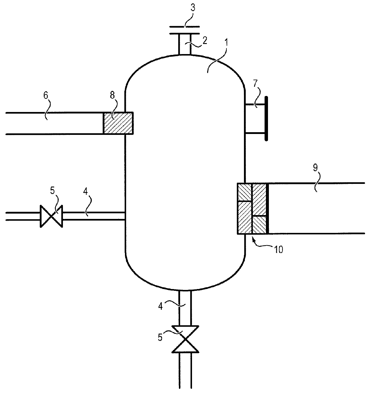
[0043]FIG. 4 is a schematic view of a tank comprising the plug according to the invention with an instrumentation system;
second embodiment
[0044]FIG. 5 is a sectional view of the plug according to the invention placed inside a pipe to be sealed;
[0045]FIG. 6 is a view of the plug of FIG. 5 along the plane A-A, representing the position holding device;
[0046]FIG. 7 is a perspective view of the plug of FIG. 5;
[0047]FIG. 8 is a schematic representation, side view, of the anti-extrusion system of the plug according to the invention;
[0048]FIG. 9 is a schematic representation, frontal view, of the anti-extrusion system of FIG. 8.
Login to View More PUM
 Abstract
The invention relates to a plug for closing and isolating a pipe (9) having an inner wall forming a substantially cylindrical cavity with a so-called first diameter, the plug comprising:a main body (110) having substantially a shape of a cylinder with a so-called second diameter, the second diameter being smaller than the first diameter to allow the plug to be inserted into the cavity; andsealing joint elements (120) that project around the side wall of the cylinder (110) defining the shape of the main body, so as to seal a free space formed between the main body (110) and the inner wall of the pipe (9),in which the main body (110) comprises several assembly elements forming the cylinder (110), each assembly element having a shape inscribed within a parallelepiped volume defined by three orthogonal dimensions, where at least two of the three dimensions have a length smaller than the second diameter, and the plug further comprising a position holding system comprising several non-slip pads (140; 340) deployable in order to assure a holding of the plug by compression, the set of non-slip pads forming an overall contact surface extending over at least half of the periphery of the section of the cylinder (110).
Description
FIELD OF THE INVENTION[0001]The present invention relates to a device which makes it possible to close a pipework, a tank or a set of tank(s) and pipe(s) in order to be able to isolate them, especially with a view to maintenance, test or hydraulic pressure testing operations.PRIOR ART[0002]Numerous industrial installations comprise enclosures (reservoirs, tanks, exchangers, etc.) coupled to pipes (pipework) for the passage of fluids, liquid or gaseous, often under pressure. In order to guarantee a reliable and secure operation of these installations, the maintenance of such systems requires regularly carrying out leak tightness tests and the regulations for pressurised devices moreover impose carrying out hydraulic pressure testing periodically.[0003]For carrying out leak tightness tests or hydraulic pressure testing of reservoirs, tanks, or any other type of enclosure, it is at present necessary to modify the configuration of the installation to create a test or testing “bubble”, t...
Claims
Login to View More Application Information
Patent Timeline
 Patent Type & AuthorityApplications(United States)
IPC IPC(8): B65D90/10F16L55/11F16L55/136
CPCB65D90/10F16L2101/30F16L55/136F16L55/11G01M3/022F22B37/221G01M3/2815
InventorNOYON, EMMANUEL
OwnerELECTRICITE DE FRANCE