System and method to prevent chemical fouling on reverse osmosis membrane

a reverse osmosis membrane and chemical fouling technology, applied in membranes, biological water/sewage treatment, multi-stage water/sewage treatment, etc., can solve the problem of reducing the permeation flow rate, and achieve the effect of reducing the cause of chemical fouling

Inactive Publication Date: 2016-02-18
MITSUBISHI HEAVY IND ENG LTD
View PDF4 Cites 15 Cited by
  • Summary
  • Abstract
  • Description
  • Claims
  • Application Information

AI Technical Summary

Benefits of technology

[0015]According to the present invention, when recycled water is produced by the reverse osmosis membrane apparatus, it is possible to prevent inflow of a contaminant into the reverse osmosis membrane apparatus and protect the reverse osmosis membrane apparatus by monitoring chemical fouling causal substance by a monitoring apparatus and by performing the operation to reduce the cause of the chemical fouling in a control apparatus.

Problems solved by technology

However, there are problems that polyamide-based materials are prone to contamination by organic matters, resulting in the decrease of permeation flow rate.

Method used


Image

  • System and method to prevent chemical fouling on reverse osmosis membrane
  • System and method to prevent chemical fouling on reverse osmosis membrane
  • System and method to prevent chemical fouling on reverse osmosis membrane

Examples


embodiment 1

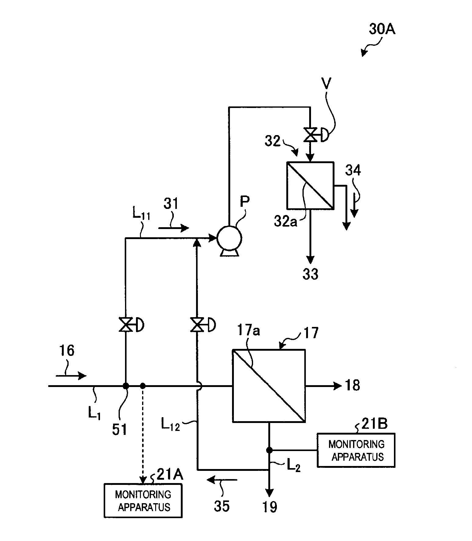
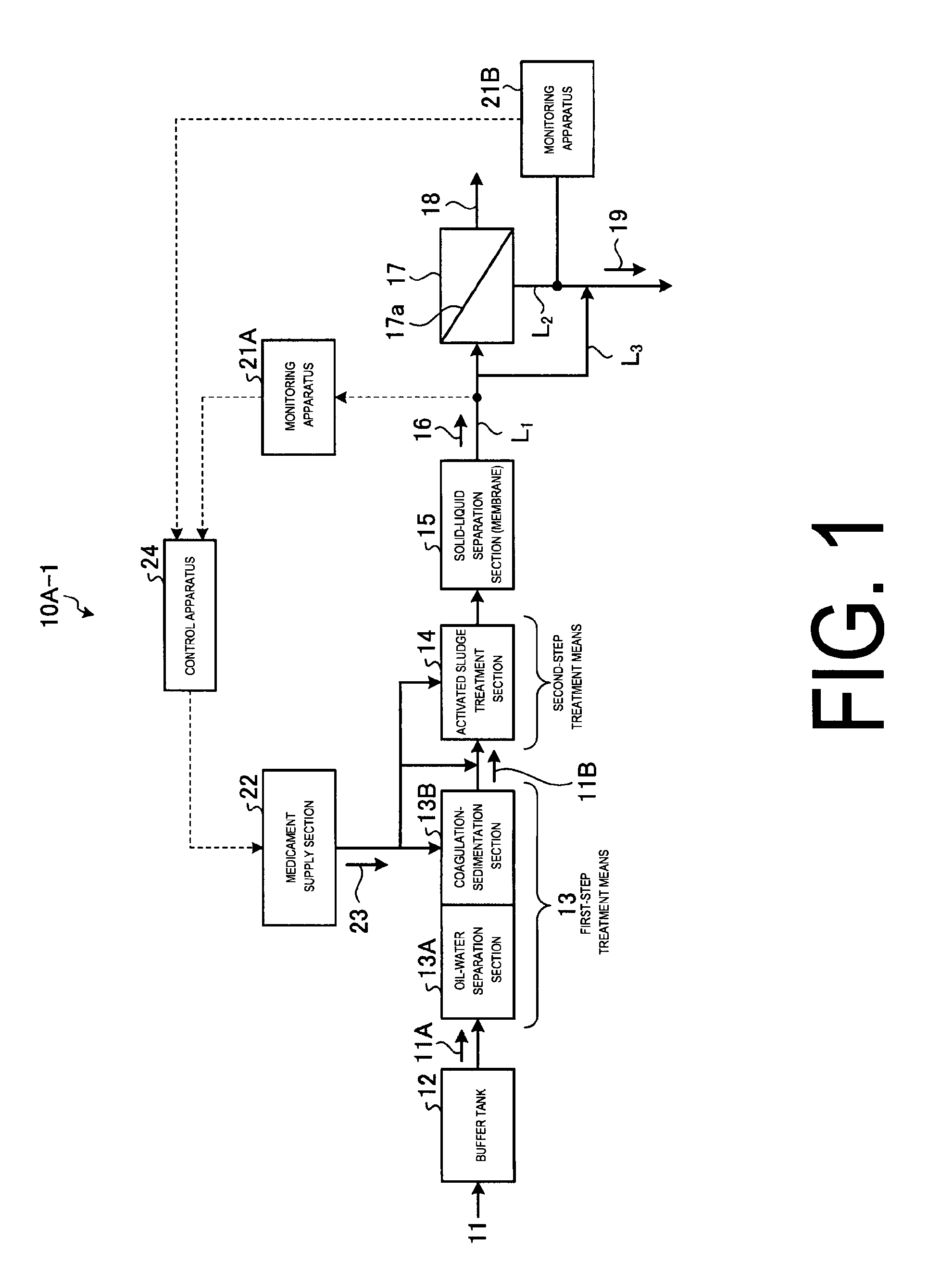
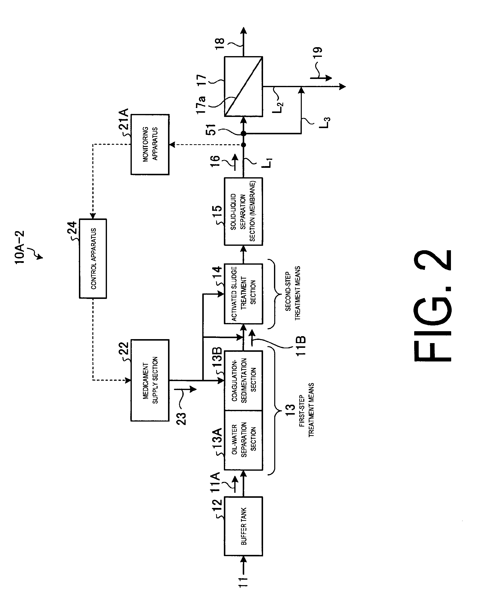
[0032]FIG. 1 illustrates a schematic view of the chemical fouling prevention system according to embodiment 1. FIG. 2 and FIG. 3 illustrate schematic views of other chemical fouling prevention systems according to embodiment 1.

[0033]As illustrated in FIG. 1, a chemical fouling preventing system 10A-1 according to the present embodiment comprises the following: a buffer tank 12 which temporally accepts and stores industrial park waste water 11; a first-step treatment means 13 which treats outflow water 11A from the buffer tank 12 as a first step; an activated sludge treatment section 14 in which outflow water 11B that is already treated by the first-step treatment means 13 is treated by microorganisms as a second-step treatment means; a reverse osmosis membrane apparatus 17 including an RO membrane 17a, which yields recycled water (permeate water) 18 with its salts removed, and concentrated water 19 with salts in industrial park waste water 11 concentrated, from pre-treated inflow wa...

embodiment 2

[0116]FIG. 9 illustrates a schematic view of the chemical fouling prevention system according to embodiment 2.

[0117]As illustrated in FIG. 9, in the chemical fouling preventing system 10B according to the present embodiment, the chemical supply section 22 is removed from the chemical fouling preventing system 10A of the embodiment 1, and an adsorption tower 52 is implemented. Since the other arrangements are the same as those in the chemical fouling preventing system 10A of the embodiment 1, the redundant members are given the same number and the redundant description will be omitted.

[0118]As illustrated in FIG. 9, the chemical fouling preventing system 10B according to the present embodiment comprises the following: a buffer tank 12 which temporally accepts and stores industrial park waste water 11; a first-step treatment means 13 which treats outflow water 11A from the buffer tank 12 as a first step; an activated sludge treatment section 14 in which outflow water 11B that is alrea...

embodiment 3

[0121]FIG. 10 is a schematic view of the chemical fouling prevention system according to embodiment 3.

[0122]As illustrated in FIG. 10, in the chemical fouling preventing system 10C according to the present embodiment, the chemical supply section 22 is removed from the chemical fouling preventing system 10A of the embodiment 1, and an electrostatic filter 53 is implemented. Since the other arrangements are the same as those in the chemical fouling preventing system of the embodiment 1, the redundant members are given the same number and the redundant description will be omitted.

[0123]As illustrated in FIG. 10, a chemical fouling preventing system 10C according to the present embodiment comprises the following: a buffer tank 12, which temporally accepts and stores industrial park waste water 11; a first-step treatment means 13 which treats outflow water 11A from the buffer tank 12 as a first step; an activated sludge treatment section 14 in which outflow water 11B that is already trea...


PUM

PropertyMeasurementUnit
chemical foulingaaaaaaaaaa
chemical monitoringaaaaaaaaaa
permeateaaaaaaaaaa

Abstract

A reverse osmosis membrane apparatus 17 including an RO membrane 17a that yields recycled water 18 and concentrated water 19 from pre-treated raw water (inflow water 16), salts being removed in the recycled water and salts being concentrated in industrial park waste water 11; monitoring apparatuses 21A and 21B disposed at an inflow water line L1 through which the inflow water 16 flows into the reverse osmosis membrane apparatus 17 or a concentrated water line L2 through which the concentrated water 19 flows out from the reverse osmosis membrane apparatus 17, which monitor the presence of chemical fouling causal substances in the inflow water 16 or the concentrated water 19; and a chemical supply section 22, which is a removal apparatus that removes the chemical fouling causal substances from the inflow water 16 on the front upstream side of the inflow into the reverse osmosis membrane apparatus 17, upon the presence of chemical fouling causal substances in the inflow water 16 or the concentrated water 19 being confirmed. Thus, the chemical fouling preventing system removes chemical fouling causal substance from inflow water 16 before it enters the reverse osmosis membrane apparatus 17.

Description

TECHNICAL FIELD[0001]The present invention relates to a system and method to prevent chemical fouling on a reverse osmosis membrane.BACKGROUND ART[0002]Conventionally, industrial waste water containing organic matter from various industries is treated by biological treatment processes such as standard activated sludge method. The standard activated sludge method is a biological treatment method of performing biological treatment of organic waste water aerobically. Waste water from various factories is treated by the first-stage treatments, such as oil-water separation treatment and coagulation-sedimentation treatment, for example, followed by the second-stage treatments such as activated sludge treatment. Then, recycled water is obtained as permeate water from a water regeneration apparatus such as a reverse osmosis membrane apparatus, for example.[0003]Examples of the reverse osmosis membranes used in the reverse osmosis membrane apparatus include polyamide-based materials. However...

Claims


Application Information

Patent Timeline
Patent Type & Authority Applications(United States)
IPC IPC(8): C02F1/44C02F1/00C02F5/00
CPCC02F1/441C02F1/008C02F2303/16C02F2103/08C02F5/00B01D61/12B01D65/08B01D2311/04B01D2311/08B01D2311/24C02F1/40C02F3/1268C02F9/00C02F2303/20Y02A20/131Y02W10/10
Inventor UKAI, NOBUYUKISUZUKI, HIDEONAKASHOJI, HIROSHIYOSHIOKA, SHIGERUEDA, MASAYUKI
Owner MITSUBISHI HEAVY IND ENG LTD
Why Eureka
Try Eureka