Sampling an oil composition and determining minimum miscibility pressure of an oil compositon with a fluid

Inactive Publication Date: 2016-02-18
ENERGY & ENVIRONMENTAL RES CENT FOUNDATIO
View PDF0 Cites 11 Cited by
  • Summary
  • Abstract
  • Description
  • Claims
  • Application Information

AI Technical Summary

Benefits of technology

The invention provides a method to determine the minimum miscibility pressure (MMP) of an oil composition and a fluid medium using simpler and less expensive instrumentation than other methods. The method is faster, more consistent, and less operator dependent than other techniques. It can accurately measure the MMP without reaching the pressure during the method and without needing to measure the density of the oil or fluid phase. The method can extrapolate the MMP from a linear plot, resulting in greater speed and accuracy. It is also simpler and less expensive to perform multiple MMP determinations, allowing investigation of the effect of different parameters on MMP. Overall, the method provides a more efficient and cost-effective way to evaluate oil composition and parameters that affect MMP.

Problems solved by technology

However, there exists no standard design, standard operating procedure, and no standard set of criteria for determining MMP using slim-tube tests.
Moreover, the slim-tube test's definition of miscibility as the break-over point in the oil recovery-versus-pressure curve requires several slow-rate slim-tube displacement tests, and hence, this technique is costly and time-consuming (4-5 weeks).
However, the extrapolation in Rao's VIT technique is difficult since it is performed using a curve whose slope increases as it nears the axis with which the point of intersection must be determined.
Additionally, Rao's VIT technique requires extremely accurate measurements of capillary tube inner diameter, and requires a tedious measurement of the density of each phase under each of the pressure and temperature conditions tested.

Method used


Image

  • Sampling an oil composition and determining minimum miscibility pressure of an oil compositon with a fluid
  • Sampling an oil composition and determining minimum miscibility pressure of an oil compositon with a fluid
  • Sampling an oil composition and determining minimum miscibility pressure of an oil compositon with a fluid

Examples


embodiment 1

[0067 provides a method of determining a minimum miscibility pressure of a fluid with an oil composition, the method comprising:

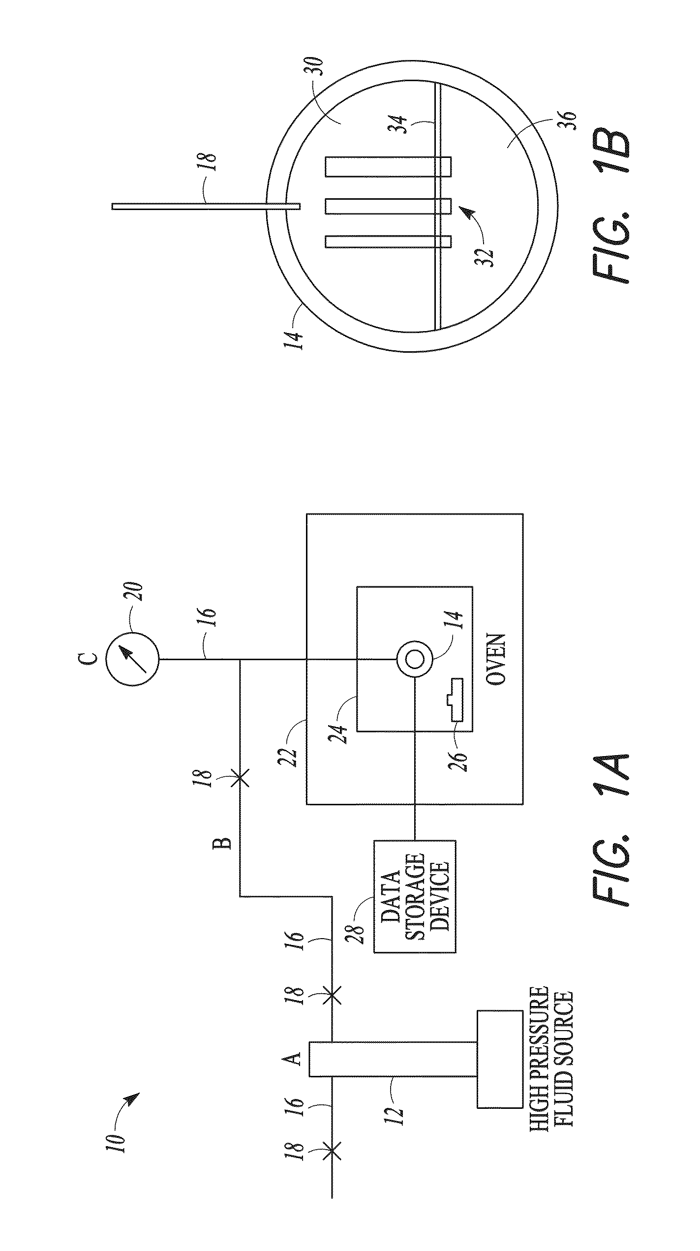
[0068]placing a fluid into a pressure chamber at a first pressure, the pressure chamber comprising at least one capillary tube having one end disposed in an oil composition in the pressure chamber, wherein the fluid comprises at least one of a gas, a liquid, and a supercritical fluid;

[0069]measuring a height of the oil composition in at least one of the capillary tubes;

[0070]repeating the measuring for at least one cycle using a second pressure different than the first pressure; and

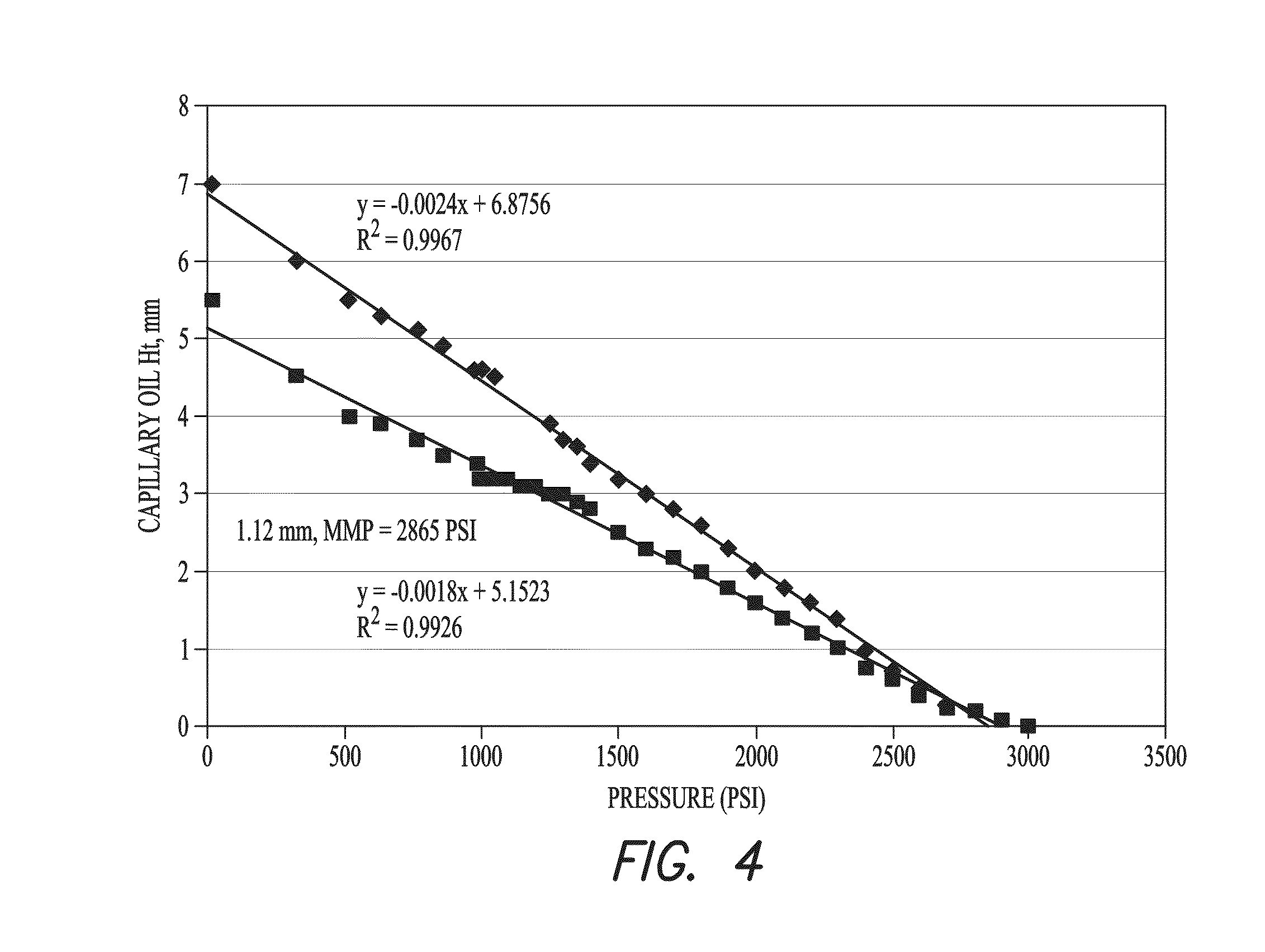
[0071]determining the minimum miscibility pressure of the oil composition with the fluid by extrapolating the pressure at a height of the oil in the at least one capillary tube of zero from the two or more measurements of the height of the oil composition in the at least one capillary tube.

[0072]Embodiment 2 provides the method of Embodiment 1, further comprising equilibrating pr...

embodiment 27

[0097 provides a method of flooding a subterranean formation with a fluid, the method comprising:

[0098]obtaining or providing a maximum pressure for a subterranean formation;

[0099]performing the method of any one of Embodiments 1-26 using as the oil composition a sample from the subterranean formation or that substantially resembles a sample from the subterranean formation;

[0100]adjusting the composition of the fluid and repeating the performance of the method, until at least one fluid composition is determined that has a lower minimum miscibility pressure with the oil composition than the maximum pressure for the subterranean formation; and

[0101]performing a flooding treatment of the subterranean formation using the fluid at a pressure that is equal to or above the determined minimum miscibility pressure and below the maximum pressure for the subterranean formation.

embodiment 28

[0102 provides a method of determining a minimum miscibility pressure of a fluid with an oil composition, the method comprising:

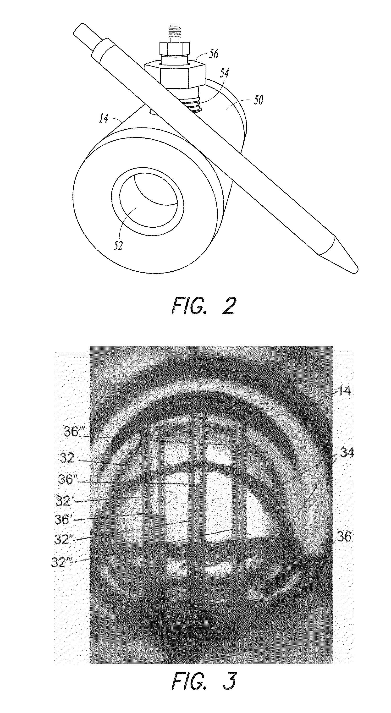
[0103]placing a fluid into a pressure chamber at a first pressure, the pressure chamber comprising a plurality of capillary tubes each having one end disposed in an oil composition in the pressure chamber and each having a different inner diameter, wherein the fluid comprises at least one of a gas, a liquid, and a supercritical fluid comprising at least one of carbon dioxide, nitrogen, methane, ethane, propane, hydrogen sulfide, n-butane, iso-butane, natural gas, natural gas liquids, and produced gas, wherein the oil composition comprises at least one of crude oil, a crude oil fraction, a mixture substantially resembling crude oil, and a mixture substantially resembling a crude oil fraction;

[0104]measuring a height of the oil composition in each of the capillary tubes;

[0105]repeating the measuring for at least one cycle using a second pressure different tha...


PUM


Abstract

Various embodiments disclosed relate to methods and apparatuses for determining a minimum miscibility pressure of a fluid with and oil composition. In various embodiments, the method can include placing a fluid into a pressure chamber at a first pressure. The pressure chamber can include at least one capillary tube having one end disposed in an oil composition in the pressure chamber. The fluid can include at least one of a gas, a liquid, and a supercritical fluid. The method can include measuring a height of the oil composition in at least one of the capillary tubes. The method can include repeating the measuring for at least one cycle using a second pressure different than the first pressure. The method can include determining the minimum miscibility pressure of the oil composition with the fluid by extrapolating the pressure at a height of the oil in the at least one capillary tube of zero from the two or more measurements of the height of the oil composition in the at least one capillary tube.

Description

CROSS-REFERENCE TO RELATED APPLICATION[0001]This application claims the benefit of priority to U.S. Provisional Patent Application Ser. No. 62 / 037,740, filed Aug. 15, 2014, the disclosure of which is incorporated herein in its entirety by reference.BACKGROUND OF THE INVENTION[0002]Crude oil miscibility pressure with different fluids is an important parameter to optimize for enhanced oil recovery. The “minimum miscibility pressure,” or “MMP,” is an operating parameter that is useful for the successful operation of enhanced oil recovery processes such as the injection of fluids including, but not limited to, carbon dioxide, natural gas, and nitrogen into an oil reservoir. The injection of such fluids can increase production from the treated subterranean formation by at least one of swelling the crude oil, reducing oil viscosity, and forming a mobile phase including the injected fluid and oil components.[0003]The most common available experimental techniques to determine fluid MMP in c...

Claims


Application Information

Patent Timeline
IPC IPC(8): E21B47/06E21B43/16
CPCE21B43/16E21B47/06G01N33/2823
Inventor HAWTHORNE, STEVEN B.MILLER, DAVID J.
Owner ENERGY & ENVIRONMENTAL RES CENT FOUNDATIO
Why Eureka
Try Eureka