Compact liquid nitrogen pump

a liquid nitrogen pump and compact technology, applied in the direction of positive displacement liquid engine, piston pump, container discharging method, etc., can solve the problems of not all pumps can be adapted to operate at a flow rate much higher or lower, and many currently available cryogenic pumps are unsuitable for continuous operation, etc., to prevent cavitation of cryogenic liquid, reduce the flow rate, and reduce the cost

Active Publication Date: 2016-03-03
UCHICAGO ARGONNE LLC
View PDF6 Cites 13 Cited by
  • Summary
  • Abstract
  • Description
  • Claims
  • Application Information

AI Technical Summary

Benefits of technology

[0016]Another object of the present invention is to provide a cryogenic liquid pump that can cycle and recirculate a cryogenic liquid during a lengthy experimental procedure. A feature of the invention is that it provides a means for continuously refilling the Dewar container such that fluid pressures are maintained and do not drop within the pump. An advantage of the present invention is that a large store of cryogenic liquid is not necessary to maintain operation of the pump. A further advantage of the present invention is that small laboratories do not need to undertake the cost of building and maintaining large stores of cryogenic liquid. A still further advantage is that small laboratories do not need to devote a large portion of their supply of cryogenic liquids to a single experiment. Rather, the invented device and method can supply a plurality of systems requiring cryogenic fluid for extended periods of time, inasmuch as the capability for doing this is limited only by the fluid resistance of each circuit and the flow rates required by each system.
[0017]Still another object of the present invention is to provide a cryogenic liquid pump that can be used for small-scale laboratory experimentation. A feature of the present invention is that it is able to provide continuous flow at a low rate (approximately 2 L / min) while maintaining a pump head of two to three meters. An advantage of the present invention is that the pump is relatively small, powerful, and inexpensive compared to other state of the art cryogenic pumps.
[0018]Another object of the present invention is to provide a centrifugal pump that can operate over a relatively wide range of flow rates. A feature of the present invention is that it can operate at a flow rates between about 11 L / min and about 0.1 L / min by varying the voltage input to the motor. Another feature of the present invention is that the gas release plate allows the pump to operate at lower flow rates. Typically, when centrifugal pumps operate at a flow rate below their best efficiency point, the pumping power is converted to thermal energy because the liquid remains in the pump housing, and as a result, the temperature of the liquid in the pump housing will rise. An advantage of the present invention is that the cryogenic liquid in the Dewar container cools the liquid in the pump housing, and while some of the liquid will vaporize, the gas release plate removes the bubbles from the pump housing.
[0019]Yet another object of the present invention is to provide a cryogenic pumping system that can operate uninterrupted without technician intervention. A feature of one embodiment of the present invention is that the Dewar container storing the cryogenic liquid contains a level sensor. The level sensor triggers a valve on an exterior reservoir to replenish the Dewar container when the cryogenic liquid level falls below a certain point. An advantage of the present invention is that a technician does not need to constantly monitor the liquid level in the Dewar container to see if evaporation or leaks have reduced the liquid level to a point of insufficiency.
[0020]Briefly, the invention provides a cryogenic liquid pump system, said pump system comprising a first end having at least an insulating lid and motor; a second end, wherein the second end is a pump, said pump comprising an impeller; and a gas release plate upstream of the impeller; and a shaft disposed between the first end and the second end, wherein the motor imparts mechanical energy to the pump through the shaft.
[0021]Also provided is a method for preventing cavitation of a cryogenic liquid in a cryogenic pump, the method comprising constantly maintaining pressure on the liquid.

Problems solved by technology

Many currently available cryogenic pumps are unsuitable for continuous operation at this rate.
Further, not all pumps can be adapted to operate at a flow rate lower than their designed flow rate.
Centrifugal pumps in particular are not designed to operate at rates much higher or lower than their manufacturer's stated best efficiency flow rate.
Therefore, providing a steady stream of cryogenic liquid to some experiments is a challenge.
In some instances, meaningful observation can take days or weeks, but providing the small, constant flow of cryogenic liquid required for these long-term experiments has proven difficult.
Typically, the cryogenic liquid is continuously pumped by self-pressurization into the experimental setup and then lost downstream.
The pressure gradient driving the flow is lost in conventional methods during attempts to re-collect the liquid.
Recirculation requires liquid to flow both into and out from the reservoir, but self-pressurization pumps can only support outward flow.
Since the cryogenic liquid cannot be recovered, a very large supply of cryogenic liquid is required for the duration of the experiment.
Obtaining and maintaining such a large supply of cryogenic liquid can be difficult, especially in small laboratory setups.
Additionally, it also wastes material and effort.
Supplying the cryogenic liquid to the experimental device also provides its own difficulty.
Because cryogenic liquids are boiling, they cannot be pulled through a circuit by a downstream pump.
The types of positive-pressure devices that can withstand cryogenic temperatures are limited to centrifugal pumps inasmuch as such pumps do not contain flexible components that become brittle when exposed to extreme cold.
However, centrifugal pumps are susceptible to cavitation, which is further exacerbated by the fact that cryogenic liquids are constantly boiling.
Cavitation in a pump causes large amounts of noise, vibration, pressure pulsation, degradation of pump components, and loss of efficiency.
The problems of pump cavitation are further exacerbated if a continuous flow at a low rate is desired or if the flow resistance is high.
However, these pumps are large and extremely expensive.
Further, they are unsuitable for cooling small laboratory equipment.

Method used


Image

  • Compact liquid nitrogen pump
  • Compact liquid nitrogen pump
  • Compact liquid nitrogen pump

Examples


Embodiment Construction

[0046]The foregoing summary, as well as the following detailed description of certain embodiments of the present invention, will be better understood when read in conjunction with the appended drawings.

[0047]As used herein, an element step recited in the singular and preceded with the word “a” or “an” should be understood as not excluding plural said elements or steps, unless such exclusion is explicitly stated. Furthermore, the references to “one embodiment” of the present invention are not intended to be interpreted as excluding the existence of additional embodiments that also incorporate the recited features. Moreover, unless explicitly stated to the contrary, embodiments “comprising” or “having” an element or a plurality of elements having a particular property may include additional such elements not having that property.

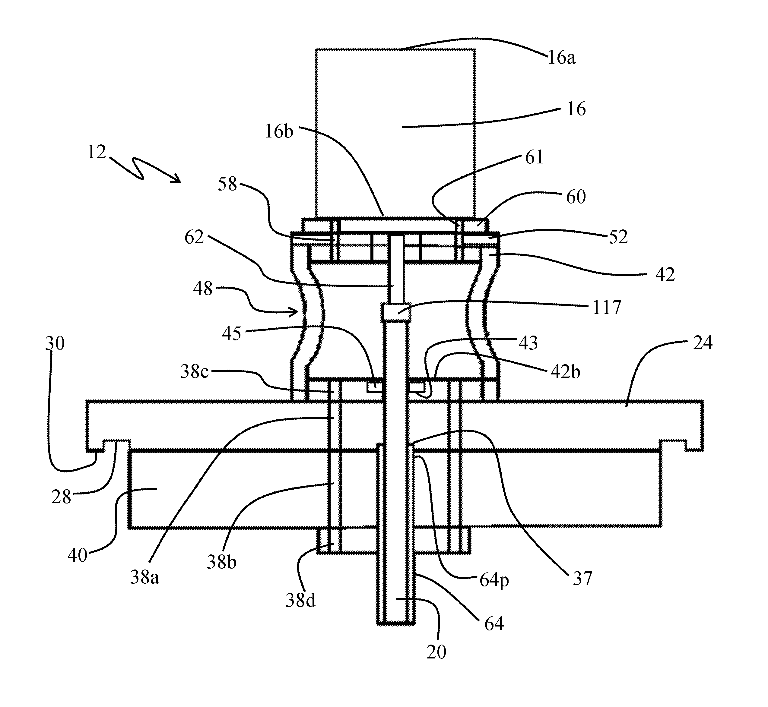
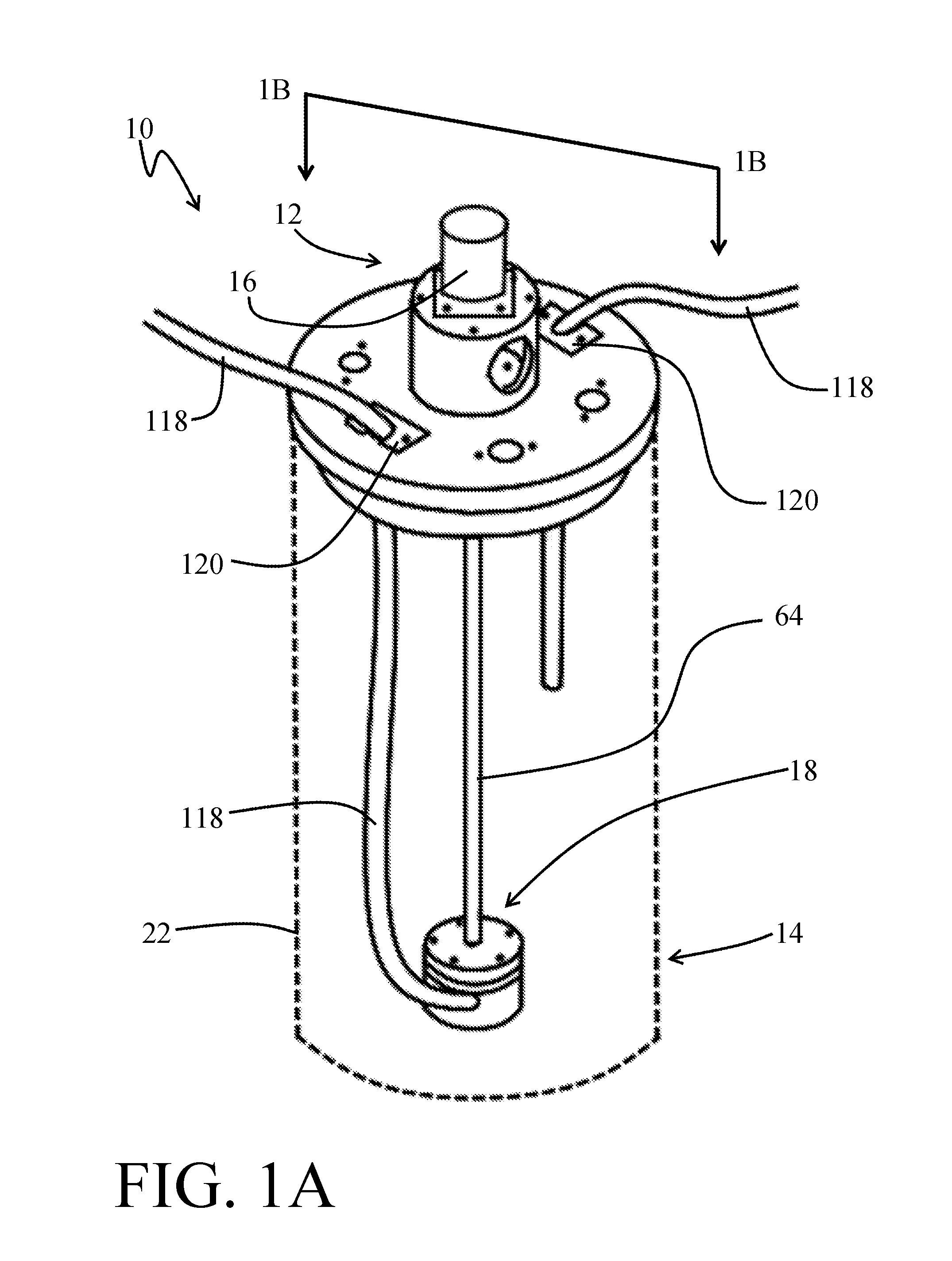
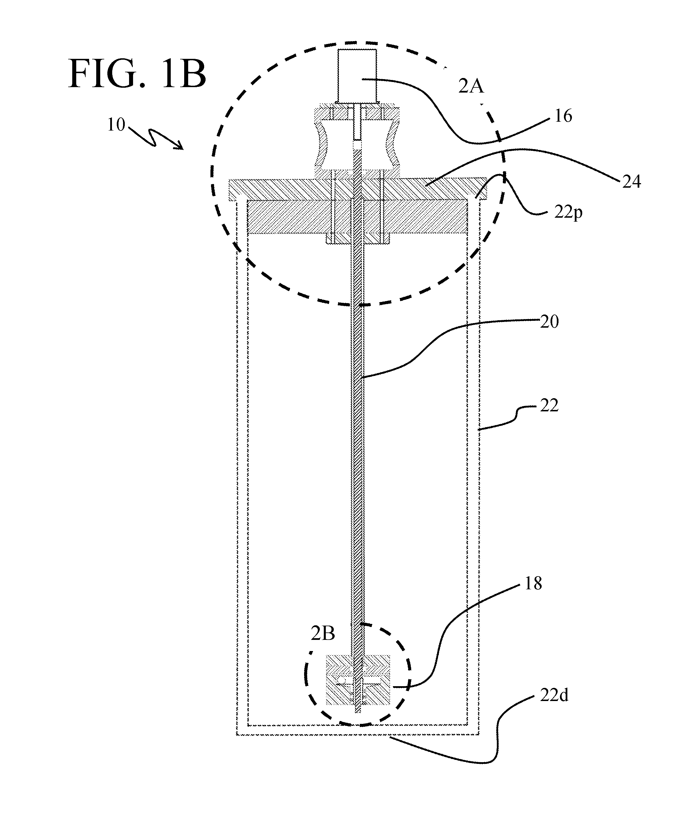
[0048]The present invention is directed to a compact cryogenic pump. The pump is designed to work at rates less than 10 L / min, and as low as 0.1 L / min.

[0049]I...


PUM


Abstract

The invention provides a cryogenic liquid pump system, having a first end with at least an insulating lid and motor; a second end, wherein the second end is a pump, said pump comprising an impeller; and a gas release plate upstream of the impeller; and a shaft disposed between the first end and the second end, wherein the motor imparts mechanical energy to the pump through the shaft. Also provided is a method for preventing cavitation of a cryogenic liquid in a cryogenic pump, the method having the steps of constantly maintaining pressure on the liquid in the pump and evacuating gas bubbles that form within the pump.

Description

CONTRACTUAL ORIGIN OF THE INVENTION[0001]The U.S. Government has rights in this invention pursuant to Contract No. DE-AC02-06H11357 between the U.S. Department of Energy and UChicago Argonne, LLC, representing Argonne National Laboratory.BACKGROUND OF THE INVENTION[0002]1. Field of the Invention[0003]The invention relates to a cryogenic fluid pump that is capable of continuously recirculating a cryogenic fluid for several weeks without user intervention.[0004]2. Background of the Invention[0005]Liquid nitrogen and other cryogenic liquids are used in a variety of scientific applications to cool experimental systems. For instance, cryogenic liquids provide favorable kinetics, confer improved vacuum conditions, and reduce the amount of contaminants in experimental procedures.[0006]Some experiments require a constant flow of a liquid cryogenic at a low rate. A “low rate” is generally considered to be a rate less than 10 L / min. Many currently available cryogenic pumps are unsuitable for ...

Claims


Application Information

Patent Timeline
Patent Type & Authority Applications(United States)
IPC IPC(8): F17C9/00F04D29/02F04D29/66
CPCF17C9/00F04D29/669F04D29/026F04D1/025F04D3/02F04D7/02F04D9/003F04D13/08F04D13/12F17C2223/0161F17C2227/0178
Inventor CALDWELL, SHANE, A.LI, GANG
Owner UCHICAGO ARGONNE LLC
Why Eureka
Try Eureka