A method and plant for carrying out thermal treatments of braking elements, in particular brake pads

a technology for braking elements and thermal treatments, which is applied in the direction of furnace components, lighting and heating apparatus, electric heating for furnaces, etc., can solve the problems of reducing the overall productivity of the plant, standard thermal treatment processes employed today do not feature sufficient flexibility, etc., and achieve the effect of reducing the dimensions of the plant and the processing duration

Active Publication Date: 2016-03-03
ITT ITAL SRL
View PDF9 Cites 0 Cited by
  • Summary
  • Abstract
  • Description
  • Claims
  • Application Information

AI Technical Summary

Benefits of technology

[0013]This arrangement permits compensation for the different durations of the two thermal treatment processes, which for the first time may be implemented within a single plant. Moreover, it makes possible extremely reduced plant dimensions and processing durations.

Problems solved by technology

However, standard thermal treatment processes employed today do not feature sufficient flexibility to allow them use the same plant to process brake pads that require thermal cycles which differ a lot one from another.
These processes also feature relatively long processing cycles, which reduce the overall productivity of the plant itself.

Method used


Image

  • A method and plant for carrying out thermal treatments of braking elements, in particular brake pads
  • A method and plant for carrying out thermal treatments of braking elements, in particular brake pads

Examples


Embodiment Construction

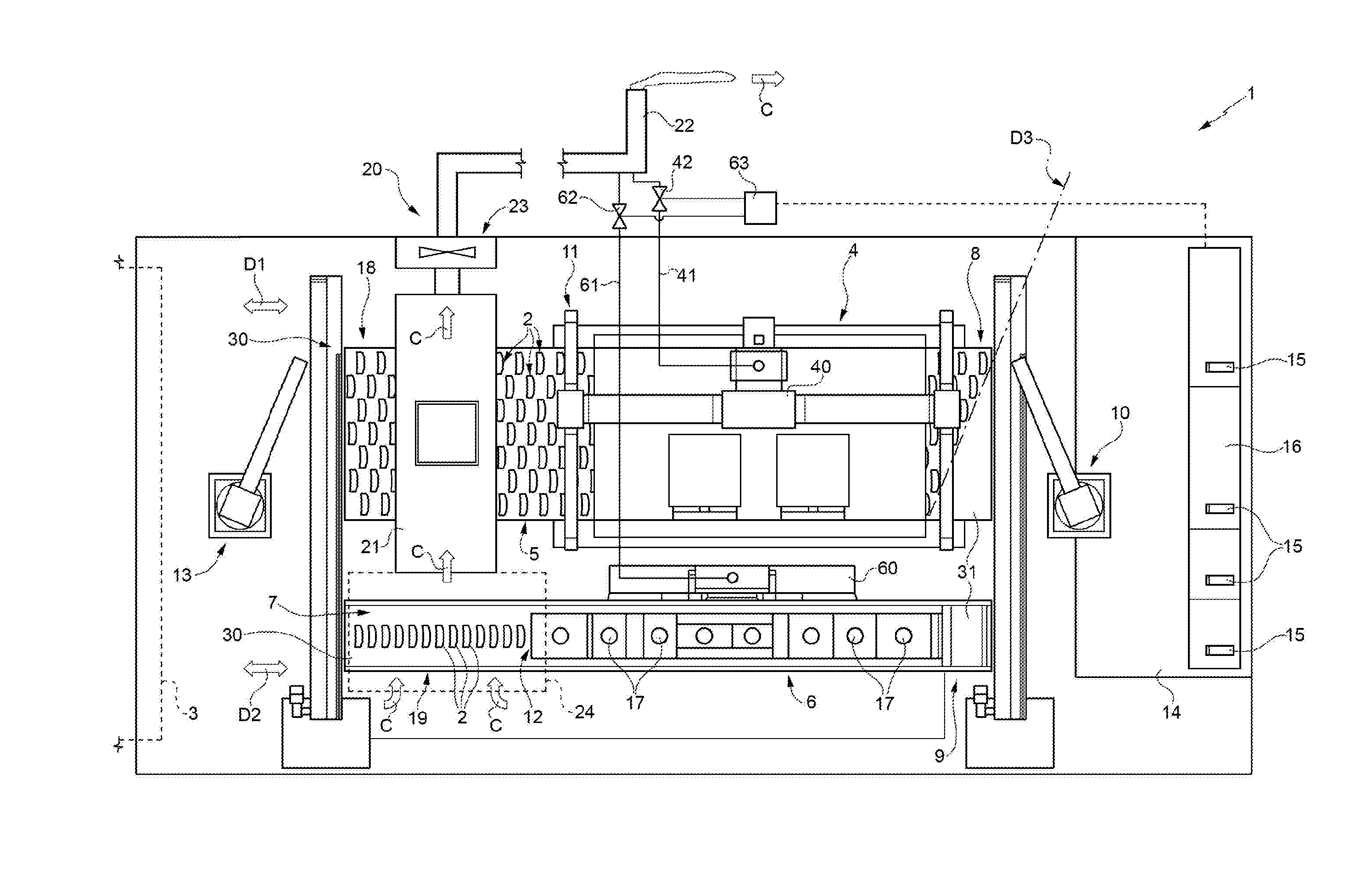
[0015]With reference to the single drawing attached, it is indicated as a whole with reference number 1 a plant for the thermal treatment of braking elements 2, in particular brake pads, which are known and illustrated for the sake of simplicity in schematic fashion only.

[0016]The plant 1 is preferably arranged immediately downstream of a station 3, known and indicated schematically with a hatched block, which is designed to carry out a known forming step upon the braking elements 2, comprising the pressing of a block of friction material on a metal support.

[0017]The braking elements 2 exit from the station 3 and from the corresponding forming step and are transferred to plant 1, preferably without allowing them to cool. The plant 1 is designed to expose the braking elements 2 to a combination of two heating processes, a convective heating process and an infrared heating process, immediately following each other.

[0018]To this end the plant 1 comprises in combination: a convection tu...


PUM

PropertyMeasurementUnit
temperatureaaaaaaaaaa
temperaturesaaaaaaaaaa
angleaaaaaaaaaa

Abstract

A method and plant for thermally treating braking elements after a forming step, including a convective heating step at 150-300° C. and a infrared irradiation heating step, immediately in succession one relative to the other. A tunnel convection furnace is crossed by at least a first conveyor belt which translates along a first direction and on an upper face of which the braking elements are placed, is arranged laterally adjacent, with respect to the first direction, to an infrared heating tunnel furnace crossed by a second conveyor belt which translates along a second direction, parallel and opposite to the first one, and on an upper face of which the braking elements are placed. The first conveyor belt is larger than the second conveyor belt, and the braking elements appear in multiple side-by-side rows in a transverse and oblique direction with respect to the first and second directions. Robots placed at the opposite ends of the furnaces transfer the braking elements from the first conveyor belt to the second one or vice versa to a first end of the furnaces and place them on the first conveyor belt or second one to a second end of the furnaces being opposite to the first one, so as to change at will the sequence in which the infrared and convective heating steps are performed.

Description

CROSS REFERENCE TO RELATED APPLICATIONS[0001]This application is a national stage application under 35 U.S.C. §371 of International Application No. PCT / IB2014 / 060386, filed Apr. 2, 2014, which claims priority of Italian Patent Application No. TO2013A000270, filed Apr. 3, 2013, the entire contents of each application being herein incorporated by reference.TECHNICAL FIELD[0002]The present invention relates to a method and plant for carrying out thermal treatments on braking elements, in particular brake pads.BACKGROUND OF THE INVENTION[0003]After the completion of the brake element forming step, the friction materials used as friction blocks in the brake shoes of drum brakes and as brake pads in disk brakes for vehicles and other equipment (such as clutch plates) must undergo a thermal treatment process which both enhances the characteristics of said materials and makes it possible to eliminate any residual gases.[0004]In particular, in the case of brake pads, the pads upon leaving th...

Claims


Application Information

Patent Timeline
Patent Type & Authority Applications(United States)
IPC IPC(8): F27B9/36F16D69/02F27B9/06F27B9/24F27B9/30
CPCC21D9/0056F27D11/12C21D1/34F16D69/00F16D2069/0491F16D2250/0092F16D2200/0082F16D69/02F27B9/066F27B9/24F27B9/3005F27B9/243F27B9/3077F27B9/36C21D9/0068
Inventor DE, DOMINICIS, SANDRO
Owner ITT ITAL SRL
Why Eureka
Try Eureka