
Cutting inserts with honeycomb sandwich structure for cooling

a sandwich structure and cutting insert technology, applied in boring/drilling components, turning machine accessories, manufacturing tools, etc., can solve the problems of not being able to cool down the top face and the bottom face, and the inserts outside are not able to cool down, so as to maintain the effect of effective cooling of the tool and adequate strength

Inactive Publication Date: 2016-03-10
WANG ANDREW T +1
View PDF5 Cites 15 Cited by
  • Summary
  • Abstract
  • Description
  • Claims
  • Application Information

AI Technical Summary

Benefits of technology

The patent text explains that a wide variety of honeycomb structure arrangements provide strong support for cutting advanced materials while also effectively cooling the tool. This is the technical effect of the patent.

Problems solved by technology

However, the outside of the insert, including most part of the top face and the bottom face are not coolant permissible, except some locations on the rake face and flank face, and also some portions on the side of the insert are also in honeycomb structure, allowing coolant going in from the tool holder.

Method used


Image

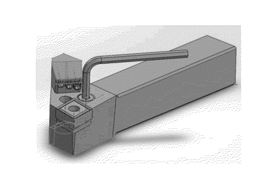
  • Cutting inserts with honeycomb sandwich structure for cooling
  • Cutting inserts with honeycomb sandwich structure for cooling
  • Cutting inserts with honeycomb sandwich structure for cooling

Examples


Embodiment Construction

[0032]Referring to the drawings, there should be an appreciation that the cutting insert of the invention, as well as the cutting assembly of the invention, can operate in a number of different applications. The cutting insert, which has internal coolant delivery, are for use in advanced material cutting, regular metal cutting, and oil / gas drilling. In this respect, the cutting insert is often used in a chip forming material removal operation wherein there is enhanced delivery of coolant adjacent the interface between the cutting insert and the work-piece (i.e., the insert-chip interface) to diminish excessive heat at the insert-chip interface.

[0033]The internal delivery of coolant to the insert body leads to certain advantages. For example, it results in lower temperature at the insert-chip interface which decreases the tendency of the chip to stick to the cutting insert.

[0034]The interior coolant passage discharge has an orientation whereby the coolant reaches beneath the rake fac...


PUM

PropertyMeasurementUnit
cross-sectional areaaaaaaaaaaa
areaaaaaaaaaaa
diversion anglesaaaaaaaaaa

Abstract

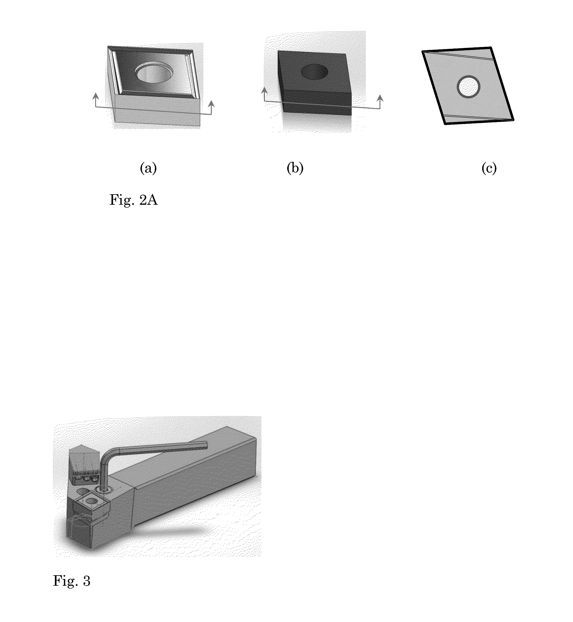
A new type of cutting insert is disclosed here which has sandwich structure often with honeycombs in the mid-section of the insert, to allow fluid and / or gas coolant flow through the insert from inside and reduce cutting tool temperature during work-piece cutting operation. The cutting insert includes an insert body, which includes cutting edge, nose, rake face, and flank face. The cutting insert body further contains interior coolant passageways formed by specially manufactured honeycomb structure in the insert body. The number, shape, and size of honeycomb interior passageways are carefully developed and distributed inside the insert body. Therefore, the insert provides adequate strength to withstand force and impact from cutting work-piece and also in the meantime provides effective cooling to the cutting tool. The honeycomb interior coolant passageways could be connected from the insert to the tool holder through an internal passageway in the tool holder, then to the coolant circulation system provided to the cutting tool, or directly connected to an external coolant circulation system. The cutting insert can be used in metal cutting, such as high strength aerospace materials and heat resistance materials. It can also be used in drilling tools for mine / oil / natural gas exploration.

Description

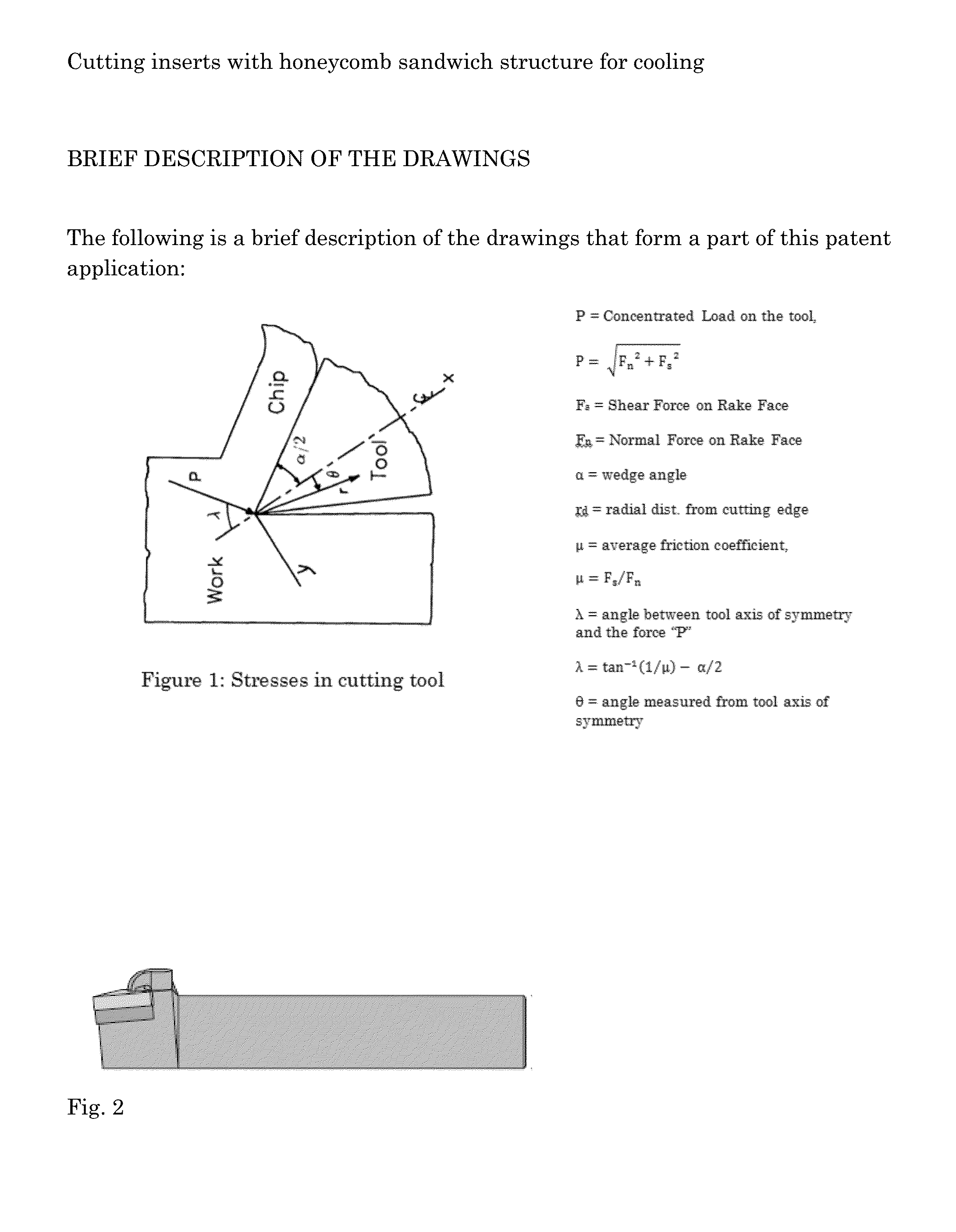
BACKGROUND OF THE INVENTION[0001]The invention relates to a cutting insert, which has honeycomb internal structure and / or internal channel(s) and pin hole(s) on rake and flank faces adjacent to cutting edge for coolant delivery, and an assembly using the cutting insert for use in the chip forming removal of material from a work-piece. More specifically, the invention pertains to a cutting insert, as well as an assembly using the cutting insert, used for chip-forming material removal operations wherein there is enhanced delivery of coolant to the insert and the interface between the cutting insert and the work-piece (i.e., the insert-chip interface) to diminish excessive heat at the insert-chip interface.[0002]In a chip-forming material removal operation (such as turning, milling, drilling, grinding, and the like), heat is generated mostly at the interface between the cutting insert rake face and the newly formed chip surface, the interface between the insert flank face and the newly...

Claims


Application Information

Patent Timeline
Patent Type & Authority Applications(United States)
IPC IPC(8): B23B27/10E21B10/62
CPCB23B27/10B23B2250/12B23B2228/36E21B10/62B23B27/141E21B10/46
Inventor WANG, ANDREW T.WANG, ZHIYONG
Owner WANG ANDREW T
Learn More