System and method of marking articles coated with a laser-sensitive material

a laser-sensitive material and coating technology, applied in the field of systems and methods for marking three-dimensional surfaces coated or doped with laser-sensitive materials, can solve the problems of inability to effectively accommodate barcodes, inability to apply labels, and possible falling off of labels made of adhesive glue, etc., and achieve the effect of high cos

Inactive Publication Date: 2016-03-17
CALIFORNIA ADVANCED LABELING
View PDF11 Cites 18 Cited by
  • Summary
  • Abstract
  • Description
  • Claims
  • Application Information

AI Technical Summary

Benefits of technology

[0020]The combination of pad printing, or tampography of, curved surfaces of items with a laser-sensitive, color-changing material may be advantageous as an alternative to applying laser-sensitive material with an adhesive (which may tear or become wet and relatively illegible under harsh conditions, or may cause the items to not fit satisfactorily in tight tolerance machines) or by doping the item itself at what may be a relatively high cost, or may allow fo

Problems solved by technology

However, it also may be laborious, may be prone to human error, may be inconsistent, and may not be able to accommodate barcodes effectively.
However, the process of applying the labels may be laborious and may be inconsistently placed on the object and/or prone to error.
Furthermore, labels made of adhesive glue can possibly fall away from a vial when presented with extreme cold or hot environments or when aggressive solvents are applied.
Heat shrink tubes may also be laborious to produce and apply.
Factory marking may require less labor and may be automation-equipment friendly, however the factory marking option may be more costly and more limited in customizability.
Any variation in such geometry from manufacturer to manufacturer can cause issues with the loading mechanism.
Direct thermal transfer also may be relatively expensive and slow due to the use of ribbons.
Automated adhesive label appliers may require relatively little labor and may be applicable to a variety of tubes, however, such equipment may be relatively expensive, tube-specific, slow, and may be prone to jamming when the labeled tube is placed into secondary equipment.
; Fremont, Calif.) may offer dynamic printing on a variety of tubes as well as barcode printing but

Method used


Image

  • System and method of marking articles coated with a laser-sensitive material
  • System and method of marking articles coated with a laser-sensitive material
  • System and method of marking articles coated with a laser-sensitive material

Examples


Embodiment Construction

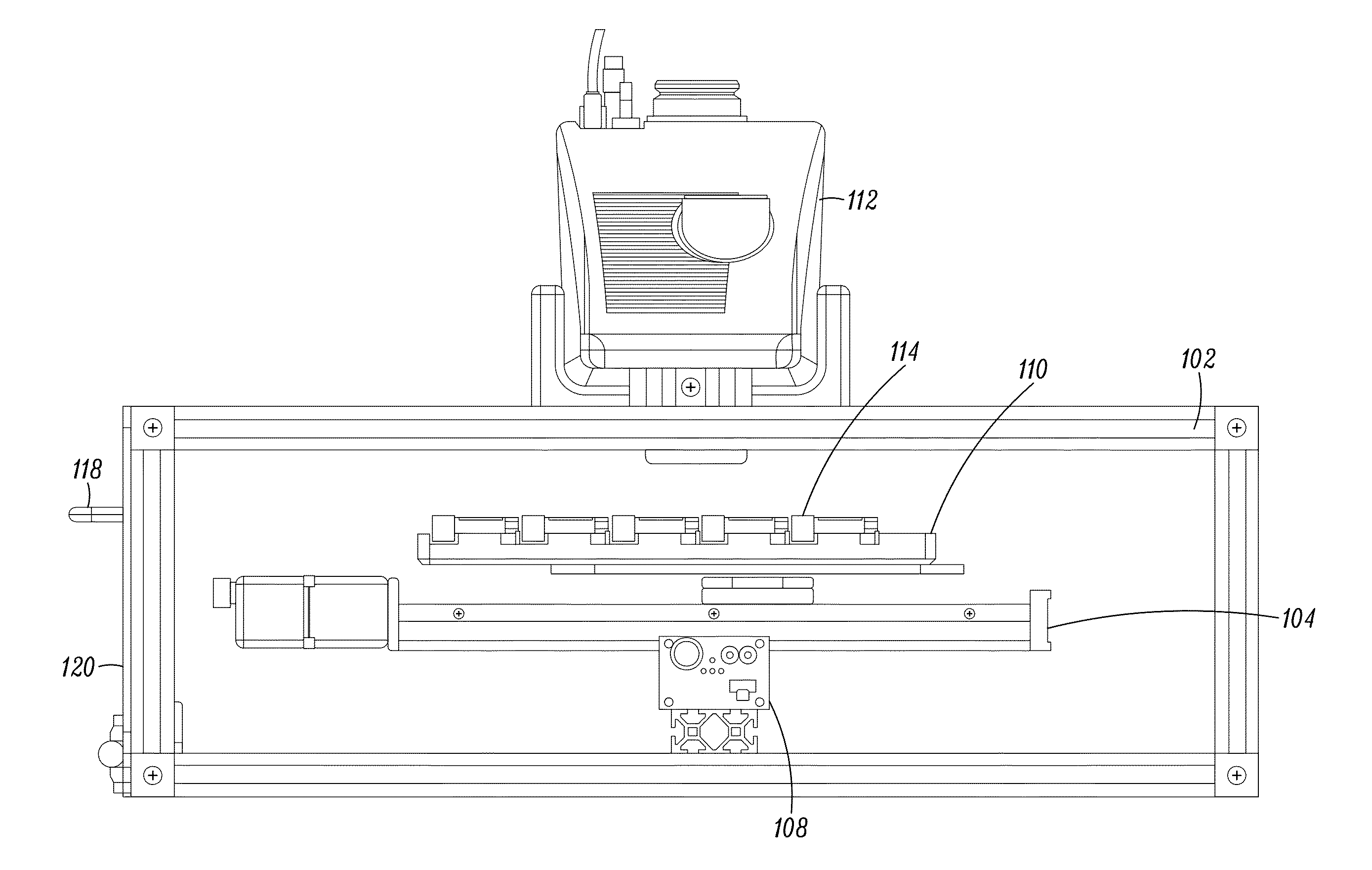
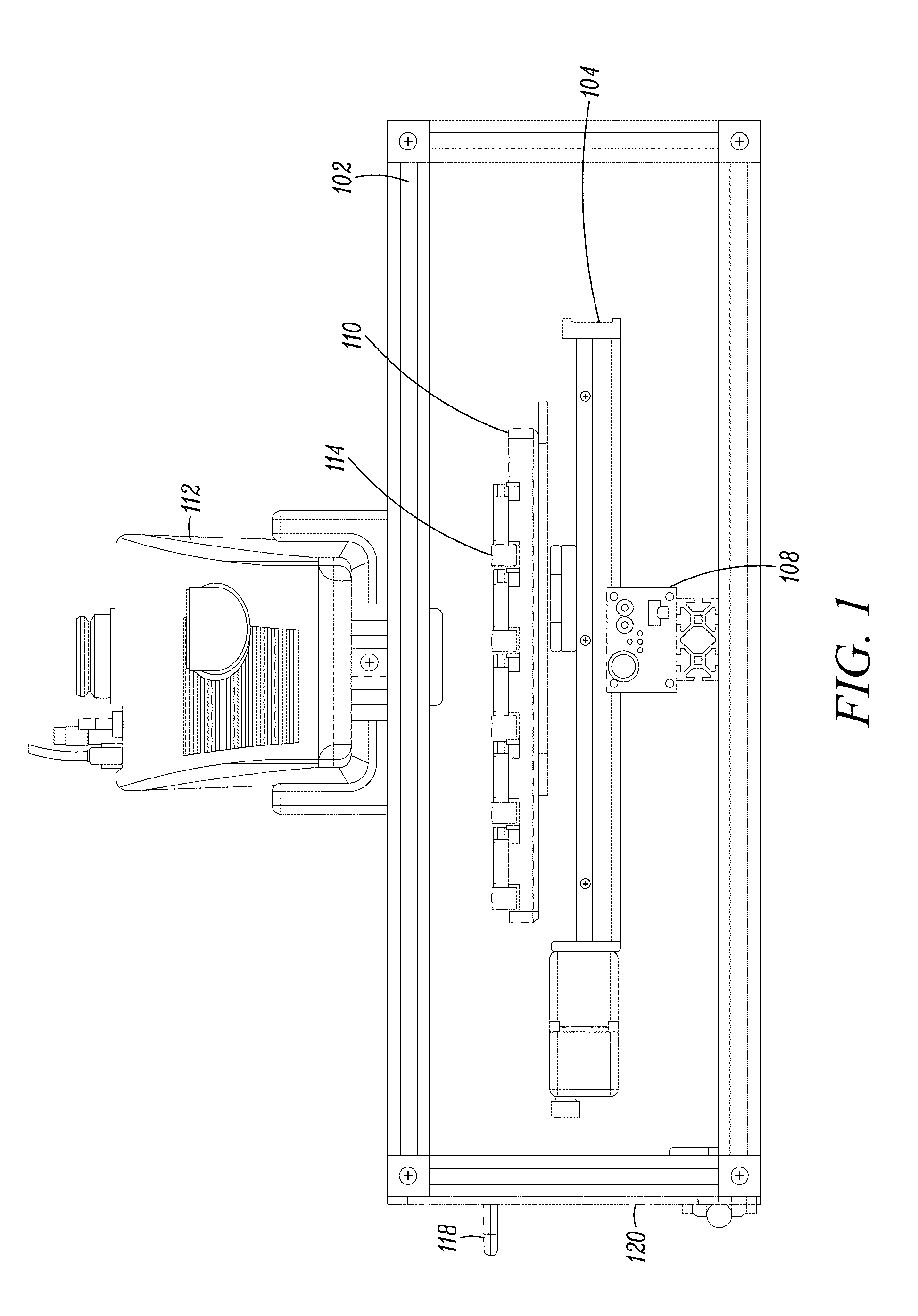
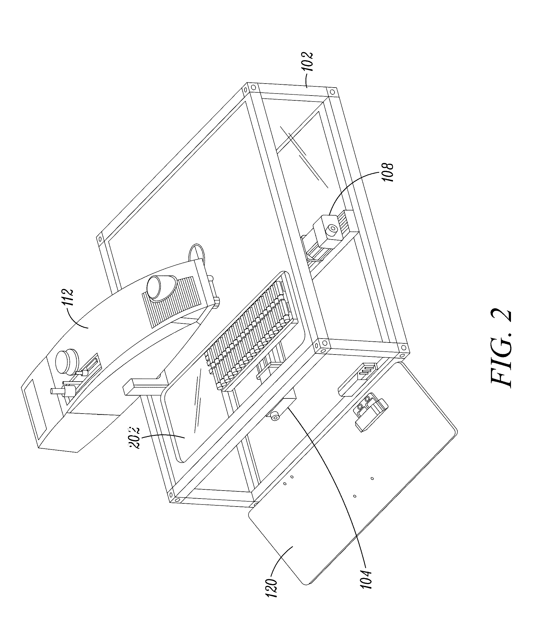
[0050]In an aspect, a laser-marking system for surfaces of articles, such as plastic or glass tubes, polypropylene, polystyrene or polyethylene articles, vials, cryovials, cryogenic vials, microcentrifuge tubes, culture tubes, microtubes, strips of tubes, blood tubes, clinical test tubes, custom-made tubes that have yet to be designed, histo-cassettes, microplates, 96-well plates, cell culture plates, microcentrifuge tubes, microscope slides, PCR tubes, microscope slides, petri dishes, screw cap tubes, conical tubes, snap cap tubes, cluster tubes, paper, polyolefin, foil films, corrugate and folding cartons, custom labware, and the like, may take advantage of laser-sensitive materials that can be located on the surface of the article, wherein the material, when excited by a low-power CO2 laser, is transformed.

[0051]Referring to FIG. 12, one such transformation may result in a colorimetric change in the material 1208 such that when the laser 1202 excites the material 1208 in a patter...


PUM

PropertyMeasurementUnit
Coloraaaaaaaaaa
Heightaaaaaaaaaa
Sensitivityaaaaaaaaaa

Abstract

A method for uniquely identifying tubes may include programming a motion of a laser relative to a tube pad printed with a mixture of ink and a laser sensitive material and exposing the laser-sensitive material to the laser to colorimetrically transform the material and reveal a unique identifier. A method of coating tubes includes plasma or flame treating the tube and mixing a laser-sensitive material with ink to form a mixture to pad print onto the tube. A system for identifying tubes coated with laser-sensitive material includes a laser mounted in translational relationship to a stage, a camera positioned to capture an image of a tube on a stage, a processor that receives the image and translates the laser relative to the stage in order to position the laser for marking the tube, and a laser controller to move the laser in order to mark the tube.

Description

CROSS-REFERENCE TO RELATED APPLICATIONS[0001]This application claims the benefit of the following provisional applications, each of which is hereby incorporated by reference in its entirety:[0002]U.S. Non-Provisional Application No. 62 / 048,844, filed Sep. 11, 2014; and U.S. Non-Provisional Application No. 62 / 048,847, filed Sep. 11, 2014.BACKGROUND[0003]1. Field[0004]This disclosure relates to systems and methods for marking three-dimensional surfaces coated or doped with a laser-sensitive material.[0005]2. Description of the Related Art[0006]Various methods and systems currently exist to mark the surface of tubes or vials (the terms are interchangeable and any reference herein to one, refers to both) or other objects or articles, with various advantages and disadvantages. Examples of some of such methods will be described herein, but it should be noted that some of these examples are not generally used in the life sciences field.[0007]Manual marking using a marker or pen may be inex...

Claims


Application Information

Patent Timeline
IPC IPC(8): B01L3/00B41M5/26F16L9/14
CPCB01L3/5453B01L2300/0851F16L9/14B41M5/267B01L2300/168B41M5/26B41M5/262F16L11/124F16L2201/60
Inventor RAO, NAGASATISHDUONG, QUOC
Owner CALIFORNIA ADVANCED LABELING
Why Eureka
Try Eureka