

Thermally insulated components
a technology of components and thermal insulation, applied in the direction of thermal insulation pipe protection, rigid containers, container/bottle construction, etc., can solve the problems of relatively high cost of heat shields, high installation or replacement costs, etc., and achieve the effect of reducing the cost, and improving the quality of combustion products
- Summary
- Abstract
- Description
- Claims
- Application Information
AI Technical Summary
Benefits of technology
Problems solved by technology
Method used
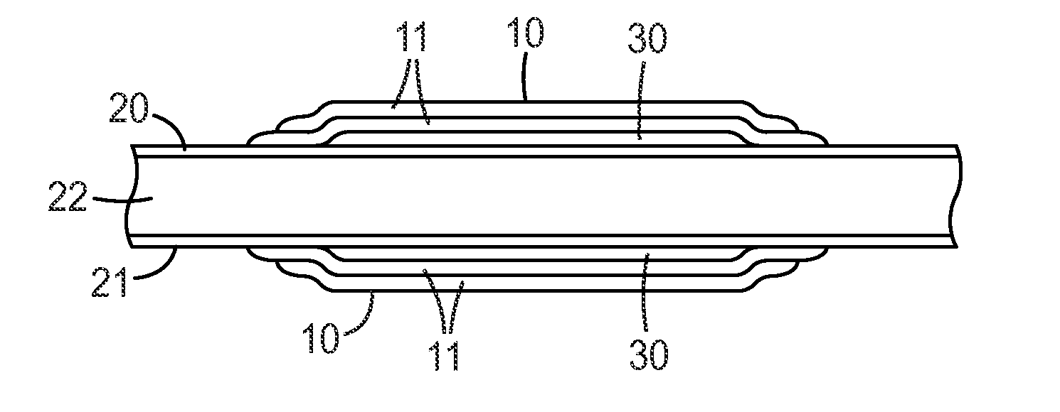
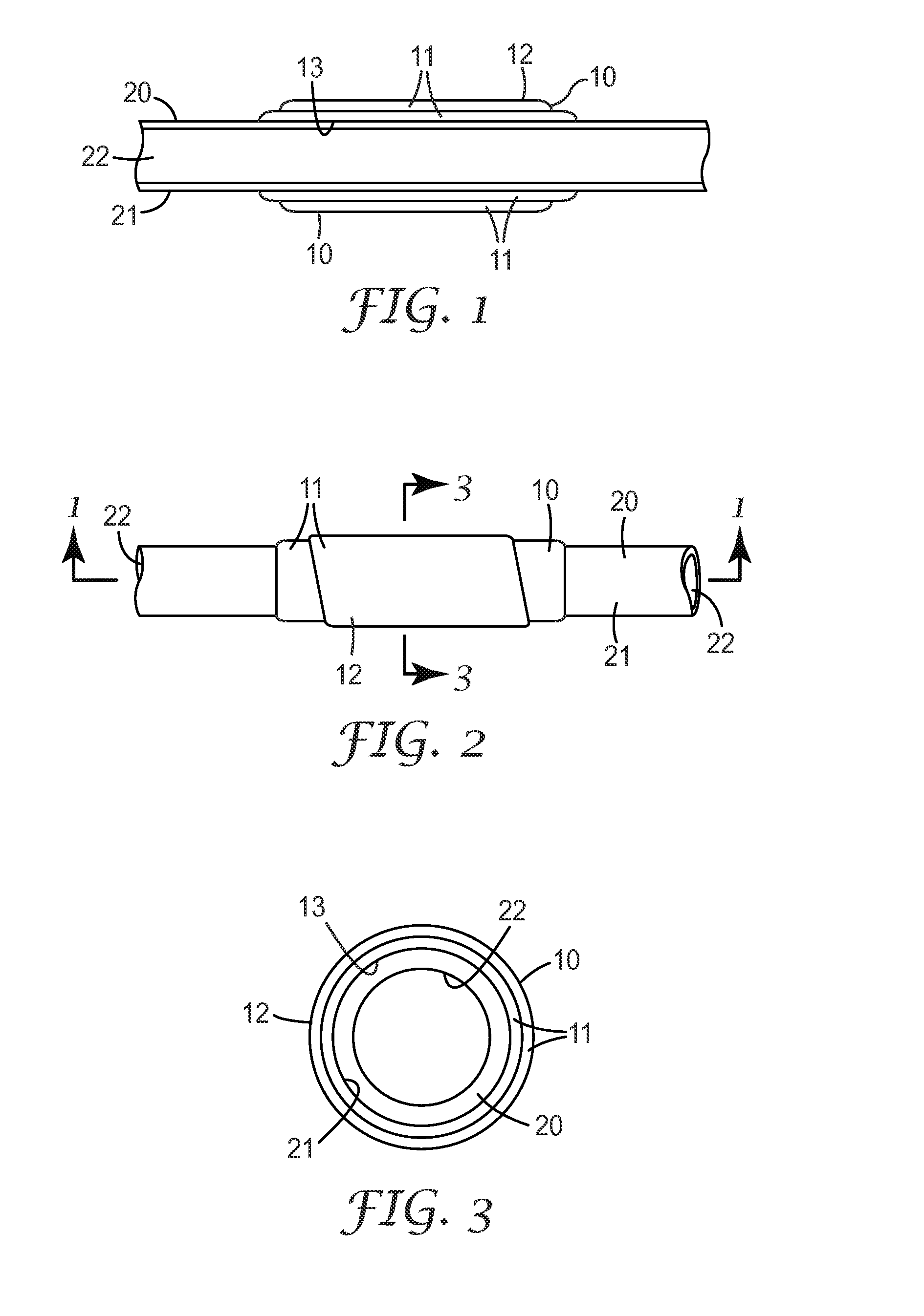
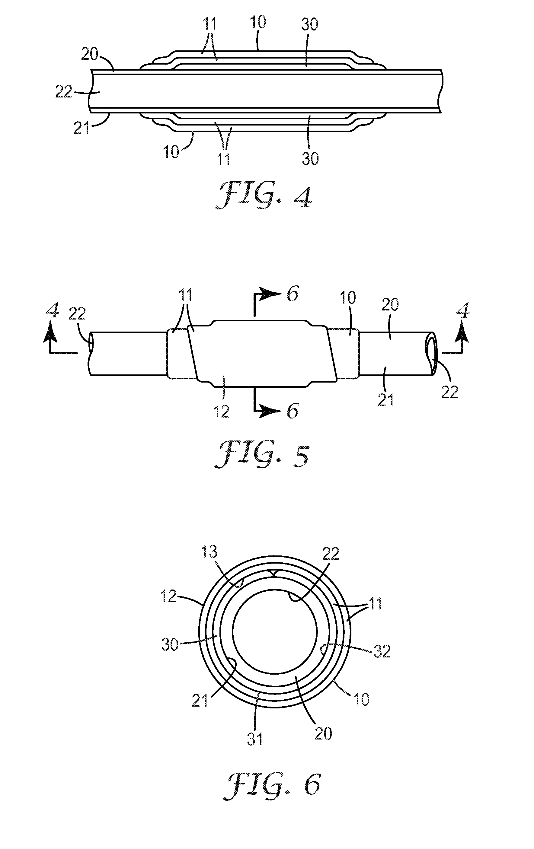
Image

Examples
example 1
[0074]Embodiments of the invention were produced by the method generally described herein.
[0075]Slurries were prepared using ingredients shown above. In each slurry, inorganic materials were added to liquid component(s) using a high shear mixer and blended until smooth to form a given slurry as shown in Table 2 below.
TABLE 2SlurriesSlurryComposition150 wt % 2327 colloidal silica, 50 wt % POLYPLATE ™ P267 wt % 2327 colloidal silica, 33 wt % calcium carbonate357.1 wt % 1144 colloidal silica, 42.9 wt % calcium carbonate494.4 wt % 2327 colloidal silica, 5.6 wt % M-5 fumed silica587.8 wt % 1144 colloidal silica, 12.2 wt % M-5 fumed silica660 wt % 2327 colloidal silica, 40 wt % talc752.9 wt % 1144 colloidal silica, 47.1 wt % talc860 wt % 2327 colloidal silica, 40 wt % silicon carbide950 wt % 2327 colloidal silica, 40 wt % aluminum powder,10 wt % POLYPLATE ™ P1082.3 wt % 2327 colloidal silica, 17.7 wt % bentonite clay1184 wt % 2327 colloidal silica, 16 wt % fumed alumina1284.4 wt % 2327 co...
example 2
[0078]Additional test samples were prepared using the procedures of Example 1. The following test samples utilized various colloidal binders. Results are shown in Table 4.
TABLE 4Test Samples and ResultsTestCoatedDryCrushSampleSlurryweight (g)weight (g)Conditionstrength N1002574.358901611012571.656.15003071022569.454.6 500 wet225103266545.990871042659.542.75001841052660.332.2 500 wet1541062765.654.2901361072760.850.65002701082761.751.3 500 Wet2121092875.658.9902171102874.3585004201112871.656.1 500 wet3601122983.152.890681132971.9475001361142972.547.3 500 wet911152471.750901731162469.148.5500260117247049 500 wet247118304931.690111193049.331.750018120305333.2 500 wet181213153.3309013.51226287.766.490961236280.561.85001871246280.862.3 500 wet1411256478.558902111266470.8535003781276467.751 500 wet33112867786090198129677256500468130677357 500 wet42813168735690122132686752500227133686853 500 wet17713469755690112135696549500211136696650 500 wet13713770725490253138706953500361139707153 500 w...
example 3
[0079]Additional test samples were prepared using the procedures of Example 1. The following test samples utilized sodium silicate binders. Results are shown in Table 5.
TABLE 5Test Samples and ResultsTestCoatedDryCrushSampleSlurryweight (g)weight (g)Conditionstrength N2003680.243.6902082014093.955.3903132024181.954902022034183.7545002422044185.656 500 wet2402054270.3647.2903832064269.846.95001312074267.7745.8 500 wet1502084454.835.9902572094461.438.9500902104463.139.7 500 wet802114566.341.7902752124559.938.75001322134560.438.9 500 wet942144668.143.9901452154660.339.55001752164659.739.2 500 wet1532175171.845.590832185159.639.55001292195245.5219032205245.52150022215245.521 500 wet22225347.622.790132235344.522.4500122245345.5122.5 500 wet72255448.625.69026226544725.3500262275446.525.2 500 wet26
PUM
| Property | Measurement | Unit |
|---|---|---|
| Length | aaaaa | aaaaa |
| Time | aaaaa | aaaaa |
| Force | aaaaa | aaaaa |
Abstract
Description
Claims
Application Information