
Gravity Field Energy Storage and Recovery System

a gravity field and recovery system technology, applied in the direction of sustainable buildings, machines/engines, mechanical equipment, etc., can solve the problems of low energy/power density, chemical batteries, added complexity and expenses,

Active Publication Date: 2016-03-24
KELLINGER JAMES FRANCIS +1
View PDF3 Cites 13 Cited by
  • Summary
  • Abstract
  • Description
  • Claims
  • Application Information

AI Technical Summary

Benefits of technology

The patent describes a system for storing and reusing potential energy without loss. This is achieved by positioning a heavy object in a gravity field and allowing it to accumulate potential energy without losing it. When the system needs to use the energy, the mass is accelerated in the gravity field and the potential energy is converted into a form that can be used by the system. The technical effect is a reliable and efficient way to store and use energy without wasting it.

Problems solved by technology

These periodic alternative energy systems then, rely on the added complexity and expenses related to energy conversion and chemical battery storage technologies.
Chemical Batteries suffer from low energy / power density, poor low-temperature performance, limited cycle life, intrinsic safety limitations, and high cost.
Also, partial charging is deleterious to the battery itself:This result has important implications to operational PV systems.
Thus, time-varying alternative energy systems rely upon a storage technology which is inherently inefficient and problematical from an operational, financial, and design standpoint.

Method used


Image

  • Gravity Field Energy Storage and Recovery System
  • Gravity Field Energy Storage and Recovery System
  • Gravity Field Energy Storage and Recovery System

Examples


Embodiment Construction

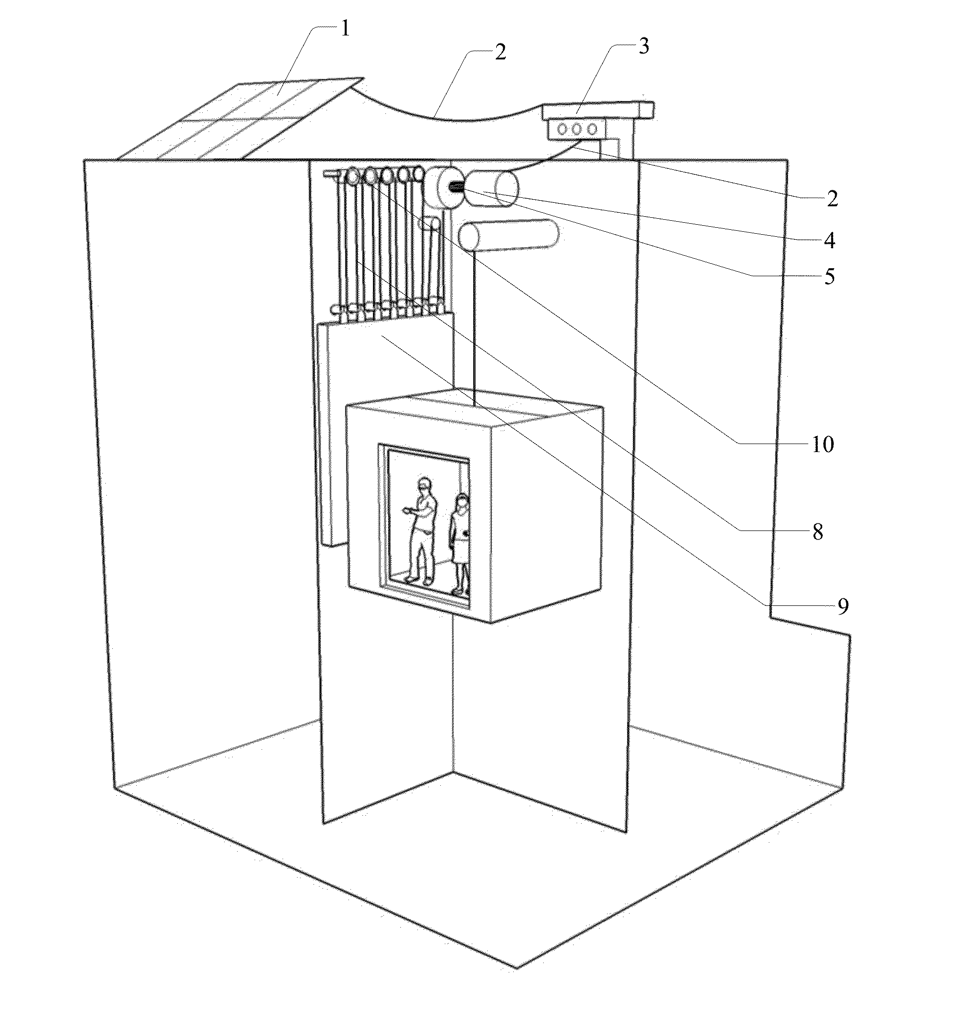
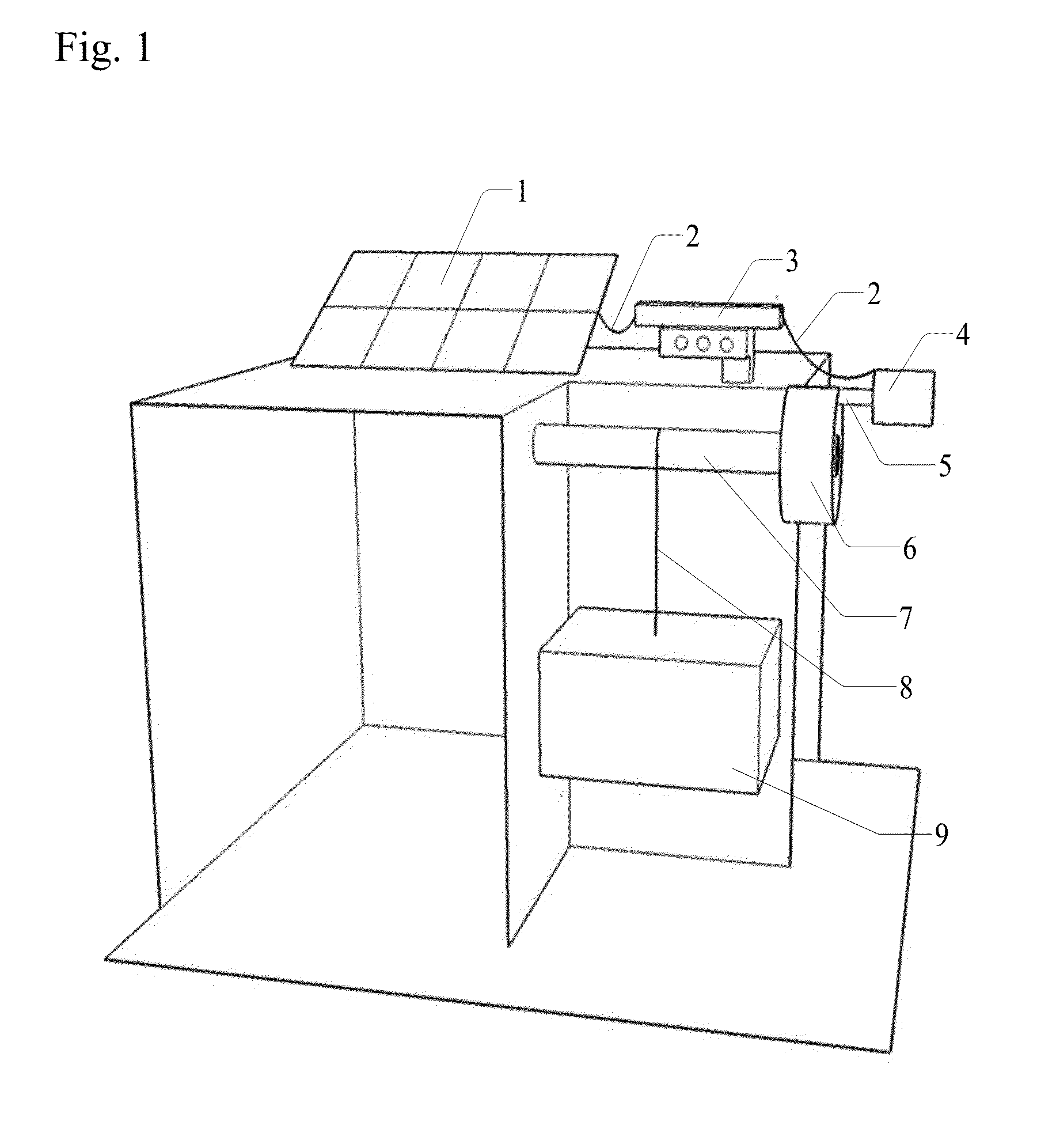
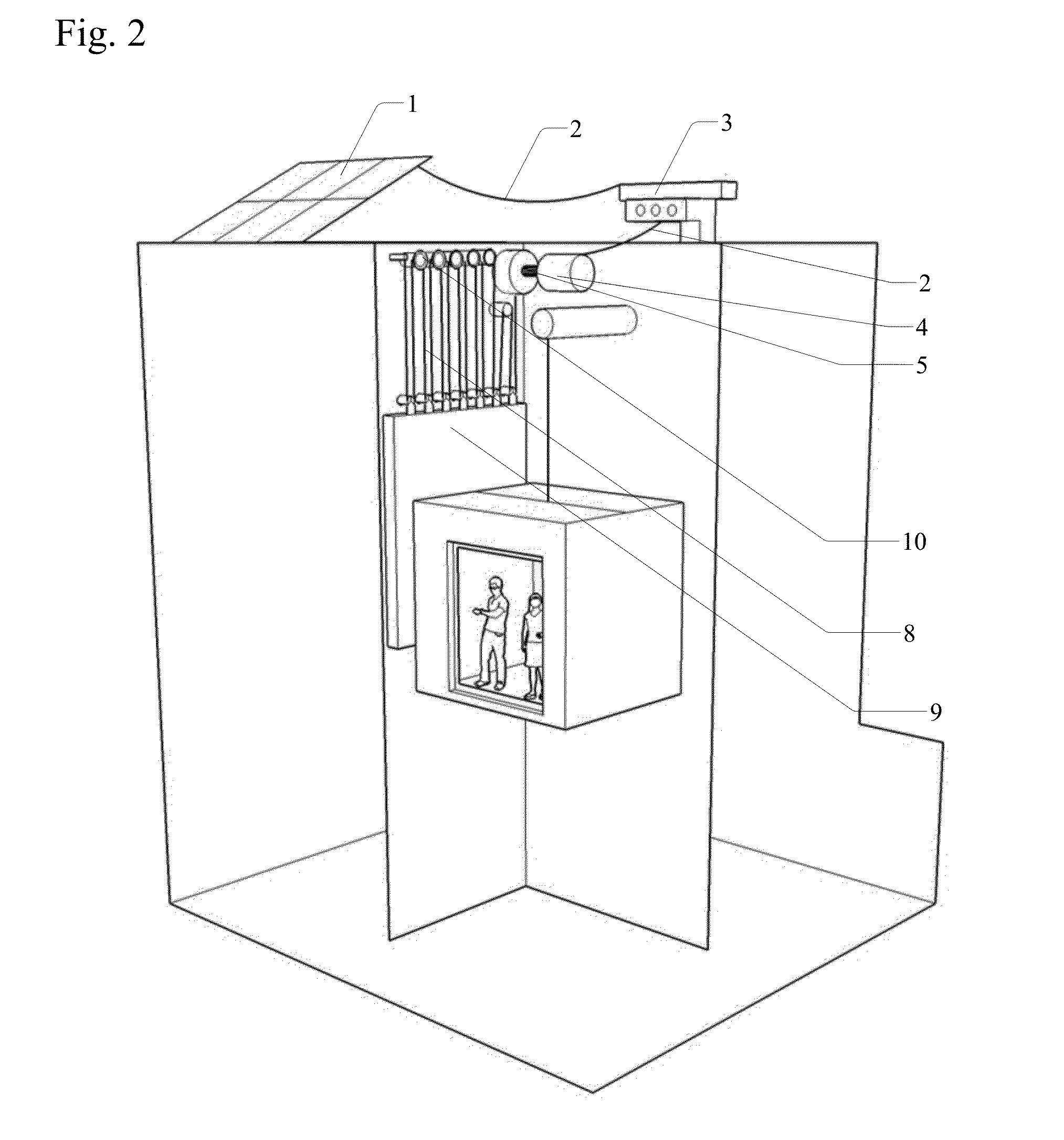
[0027]The Gravity Field Energy Storage & Recovery System [GFESRS] Invention is a mechanical, electrical and electronic system that can store energy from a variety of sources. The energy is directed at a mechanical / electrical arrangement designed to raise a large massive object in a gravitational field, storing the energy as potential energy in the field.

[0028]The Force of Gravity is described as the mutual physical attraction which every particle in the universe has with every other particle in the universe. Newton discovered the universal law of gravitation in the year 1666 and described the force of gravity as

F=GMaMbr2

[0029]Where Ma and Mb are the masses of two particles, r is the distance between the particles, and G is a constant of proportionality. The constant G was first measured by Cavendish in 1771 and the accepted value today is

G=6.67×10⁻¹¹Nm2 / kg2

[0030]A large ensemble of particles such as a planet, acts as an aggregated single object with a mass equal to the sum of the m...


PUM


Abstract

Invention defines a method and apparatus for storing energy where a power source is used to reposition a mass in a gravitational field to a position of higher potential energy where the stored potential energy may be recovered with extremely low loss regardless of the state of charge of the system, where the force of gravity may be allowed to accelerates the mass, where the resulting kinetic energy is converted to shaft horsepower. Said shaft horsepower may be converted to pneumatic, electrical, or hydraulic power. A variation defines a method where a power source is used to submerge a buoyant object in a fluid, where the submerged object represents a potential energy, where the force of gravity via the fluid, displaces the submerged buoyant object, where the kinetic energy resulting from the displacement is converted to shaft horsepower. Said shaft horsepower may be similarly converted to pneumatic, electrical, or hydraulic power. Invention defines a process where available energy can be used to do work to raise a massive object against a planetary gravitational field, to a position of high potential energy which can be maintained indefinitely. On demand the mass can be accelerated by the gravitational field and converted to kinetic energy, which is harnessed and converted to shaft horsepower, allowing the desired energy recovery from the energy storage system.

Description

BACKGROUND OF THE INVENTION[0001]1. Field of the Invention[0002]Significant advances have been made in alternative energy systems as society seeks to ameliorate the deleterious effects inherent in legacy energy systems. Fossil fuel systems rely on the combustion of hydrocarbons such as ethane, n-pentane, methane, n-octane, and coal, which, under perfect conditions, will produce heat and kinetic energy and the by-products of water and carbon dioxide. As an example, the combustion of methane in the presence of air is stoichiometric asCH4+2(O2+3.76N2)→CO2+2H2O+7.52N2 [0003]An array of hydrocarbons that are the constituents of gasoline (a well-known example is n-octane), as well as the hydrocarbons associated with coal and fuel oil, all burn in a similar fashion. Automobile engines rely on the Carnot cycle and gas turbines, powering jet aircraft and marine propulsion, rely on the Brayton cycle to harness, through a mechanical arrangement, the rapid gas expansion of the burning fuel to d...

Claims


Application Information

Patent Timeline
IPC IPC(8): F03G3/00
CPCF03G3/00F03B13/186F05B2220/708Y02B10/30Y02E10/30F03G3/087F03G3/096F03G3/094F03B13/10F03B17/02F05B2260/422F05B2260/503
Inventor KELLINGER, JAMES, FRANCISMACKAY, MICHAEL, THANE
Owner KELLINGER JAMES FRANCIS
Learn More