Coaxial direct-detection lidar-system

a lidar and coaxial technology, applied in the field of coaxial direct detection lidar system, can solve the problem of not disclosing the existence of the lidar, and achieve the effects of low maintenance requirements, low component count, and increased vibration toleran

Active Publication Date: 2016-03-24
DANMARKS TEKNISKE UNIV
View PDF4 Cites 28 Cited by
  • Summary
  • Abstract
  • Description
  • Claims
  • Application Information

AI Technical Summary

Benefits of technology

[0038]According to a second aspect, the invention is particularly, but not exclusively, advantageous for obtaining an aircraft airspeed measurement device, comprising the LIDAR system according to any one of the abovementioned embodiments. In this way, the hitherto used pitot tubes may be replaced and/or supplemented with the device according to the invention. Pitot tubes are prone to being clogged or freezing, thus giving rise to false measurements. This has been linked to several security incidents or even crashes of aircrafts resulting in loss of life. Application of the inventive LIDAR system for this use has the benefit when compared with other LIDAR systems of providing a particularly robust system, with an increased vibration tolerance and low requirements for maintenance, while comprising relatively few components. The low component count and applicability of low cost laser diode sources has the potential to provide a cost attractive LIDAR system. The inventive LIDAR system is particularly advantageous for aircraft airspeed measurements, due to the very high sensitivity resulting from the large reduction in shot noise as explained above. This is due to the fact that concentrations of aerosols in typical aircraft cruising alt

Problems solved by technology

Furthermore, the reference concerns coherent LIDARS, an

Method used


Image

  • Coaxial direct-detection lidar-system
  • Coaxial direct-detection lidar-system
  • Coaxial direct-detection lidar-system

Examples


example 1

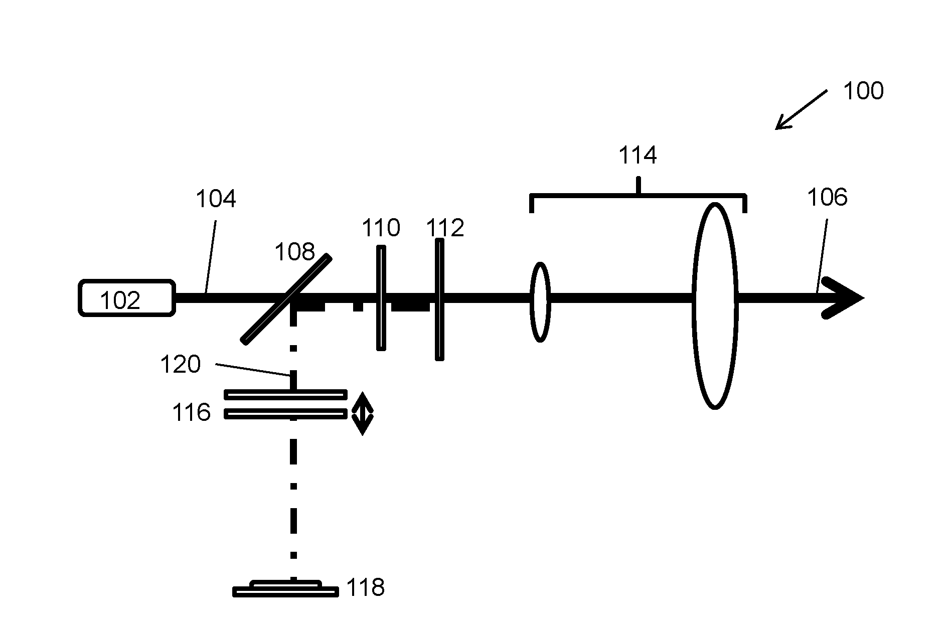
[0047]In an example relating to the embodiment shown in FIG. 1, the scanning FPI 116 has a free-spectral range (FSR) of 1 GHz and a finesse of about 500. The full-width half-maximum (FWHM) of the FPI peak is about 2 MHz. Peak transmission of the FPI at a wavelength of 1575 nm is about 14%. The laser emits at a wavelength of 1575 nm, and a femtowatt photoreceiver acts as the detector.

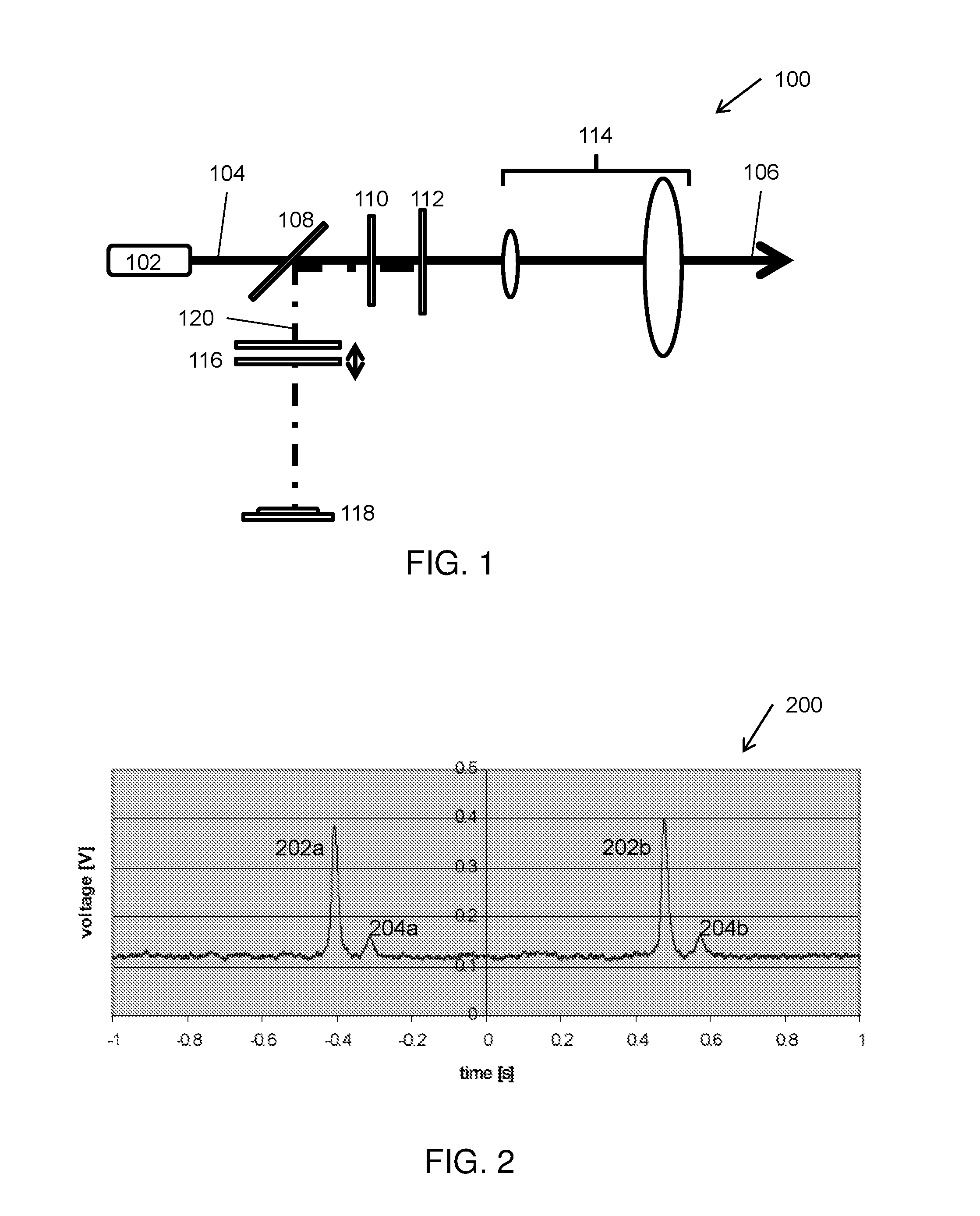
[0048]FIG. 2 shows an experimental scan 200 acquired with the system of example 1. The voltage values on the ordinate axis correspond to optical intensity measured by the detector 118, and the time values on the abscissa axis correspond to peak frequencies of the scanning FPI 116. The plot shows two scans, producing two sets of peaks 202a / 204a and 202b / 204b, respectively. The largest peaks 202a and 202b show the reference signal, i.e. indicating no Doppler shift. The smaller peaks 204a and 204b show the backscattered signal. The target used is a rotating disk, giving rise to a Doppler shift of approximat...

example 2

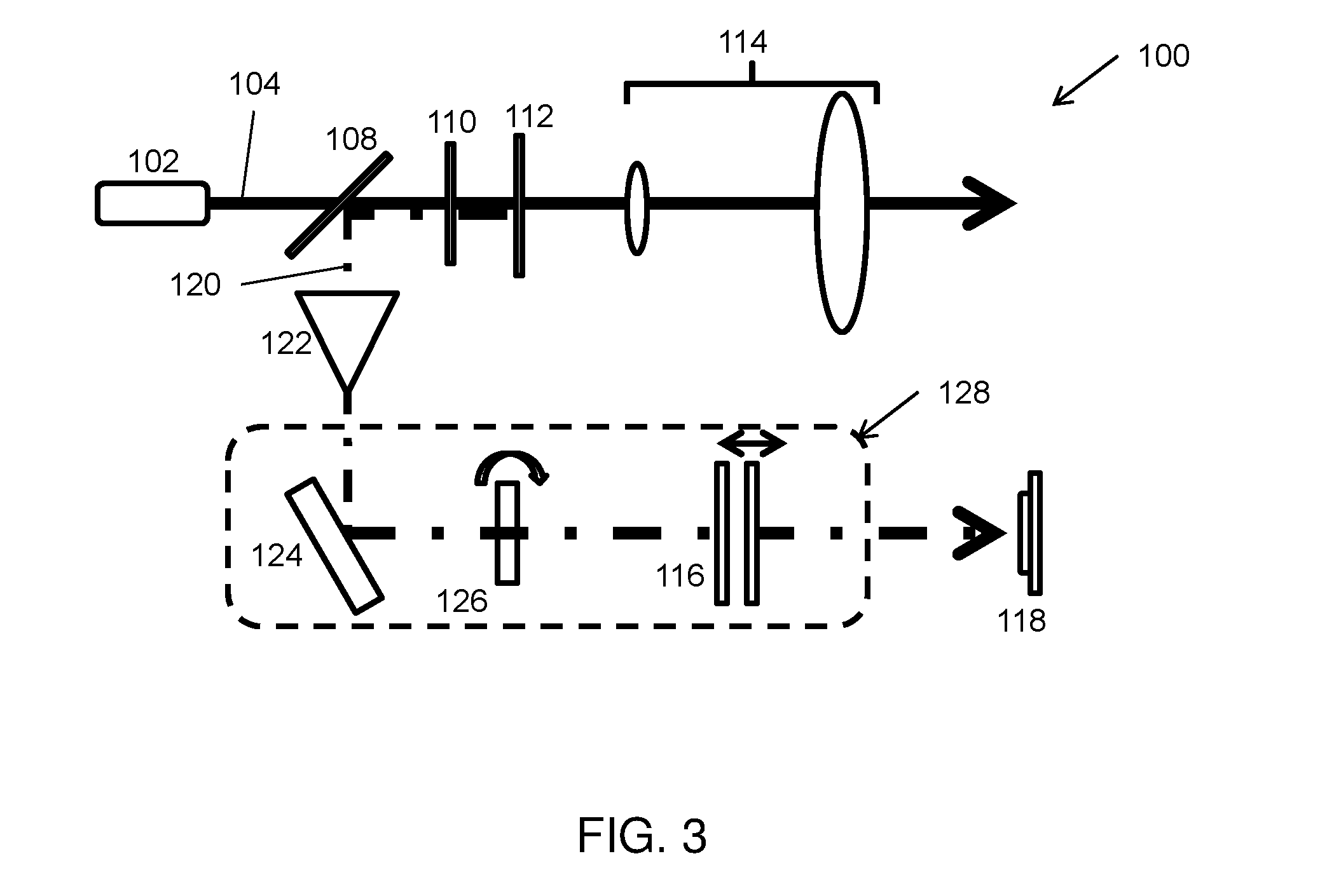
[0050]In an example relating to the embodiment shown in FIG. 3, the optical filter 124 is an optical reflection grating with a wavelength resolution of 0.2 nm. The solid FPI 126 is a 2 mm etalon with a finesse of 100. The combined tunable band-pass filter 128 has a resolution of about 2 MHz.

example 3

[0051]In an example relating to the embodiment shown in FIG. 3, the narrowband optical filter 128 suppresses the very broadband background light (and possibly ASE) by bandpass filtering in three-stages: First optical filter 124 will limit the band to about 0.2 nm or a 25 GHz band. Then static FPI 126 further reduces the band to say 100 MHz (enough to cover speeds from −40 to +40 m / s). Further noise filtering is done by the final FPI (scanning or static if the laser frequency is tunable).


PUM


Abstract

The invention relates to a coaxial direct-detection LIDAR system for measuring velocity, temperature and/or particulate density. The system comprises a laser source for emitting a laser light beam having a lasing center frequency along an emission path. The system further comprises an optical delivery system arranged in the emission path of the laser source, the optical delivery system being arranged for delivering the laser light beam in a measuring direction, the optical delivery system further being configured for collecting a return signal backscattered along the measuring direction. Finally, the system comprises a detector system arranged to receive the return signal from the optical delivery system, the detector system comprising a narrowband optical filter and a detector, the narrowband optical filter having a filter center frequency of a pass-band, wherein the center lasing frequency and/or the center filter frequency may be scanned. The invention further relates to an aircraft airspeed measurement device, and a wind turbine airspeed measurement device comprising the LIDAR system.

Description

FIELD OF THE INVENTION[0001]The present invention relates to LIDAR system for measuring velocity of remote solid or diffuse targets. More specifically, the invention relates to a coaxial direct-detection LIDAR system. For diffuse targets such as air-borne particles, the LIDAR can also be used to measure temperature and particulate density.BACKGROUND OF THE INVENTION[0002]LIDAR systems for measuring wind velocity based on Doppler shift are well known in the literature. Generally, such systems employ coherent detection (heterodyne or homodyne detection) in order to detect the small wavelength shifts associated with the Doppler shift and the weak signals backscattered to a detector of the system, by mixing the backscattered signals with a reference or local oscillator signal, and detecting the mixed signal.[0003]An example of a transmitter for a coherent Doppler LIDAR is disclosed in Marinov, et al., “Using the spectral asymmetry of TEA CO2 laser pulses to determine the Doppler-shift s...

Claims


Application Information

Patent Timeline
IPC IPC(8): G01S7/481G01S17/58G01S17/95
CPCG01S7/4812G01S17/95G01S17/58G01S7/4917Y02A90/10
Inventor RODRIGO, PETER, JOHNPEDERSEN, CHRISTIAN
Owner DANMARKS TEKNISKE UNIV
Why Eureka
Try Eureka