System and Method for Stimulated Raman Spectroscopy

Active Publication Date: 2016-03-31
MEDIZINISCHES LASERZENTRUM LUEBECK GMBH
View PDF2 Cites 13 Cited by
  • Summary
  • Abstract
  • Description
  • Claims
  • Application Information

AI Technical Summary

Benefits of technology

The invention is a system for stimulated Raman spectroscopy that is designed to detect changes in light transmission or reflection. The aim is to make the system simpler and less expensive to build.

Problems solved by technology

However, due to the small Raman scattering cross-section, pump lasers with Watt level optical output powers are usually required.
However, since the Raman signal is inherently weak, for lower sample concentrations the acquisition of a single spectrum usually takes from several seconds up to minutes.
However, again the small Raman scattering cross-section makes Raman microscopy prohibitively slow for many applications.
In almost all applications, the weak Raman cross-section is the main problem of Raman spectroscopy and Raman microscopy.
Even in cases where a long acquisition time is generally feasible, the small signal levels often make it difficult to identify the Raman signal on the fluorescence background.
While stimulated Raman scattering has been known since the 1970s (A. Owyoung, “CW STIMULATED RAMAN-SPECTROSCOPY,” Abstracts of Papers of the American Chemical Society 175, 124-124 (1978)), the lack of low noise, widely and rapidly tunable laser sources in combination with the low signal levels impeded the widespread application.
Unfortunately, however, lock-in detectors are rather expensive devices.
Accordingly, including the modality of this prior art in a microscope would severely increase its price.
A further major source of costs in ordinary Raman spectroscopy systems is the laser sources, where usually picosecond lasers or femtosecond lasers are employed, which are generally very costly as well.

Method used


Image

  • System and Method for Stimulated Raman Spectroscopy
  • System and Method for Stimulated Raman Spectroscopy
  • System and Method for Stimulated Raman Spectroscopy

Examples


Embodiment Construction

[0124]For the purposes of promoting an understanding of the principles of the invention, reference will now be made to the preferred embodiments illustrated in the drawings and specific language will be used to describe the same. It will nevertheless be understood that no limitation of the scope of the invention is intended thereby, such alterations and further modifications in the illustrated device and method and such further applications of the principles of the invention as illustrated therein being contemplated therein as would normally occur now or in the future to one skilled in the art to which the invention relates.

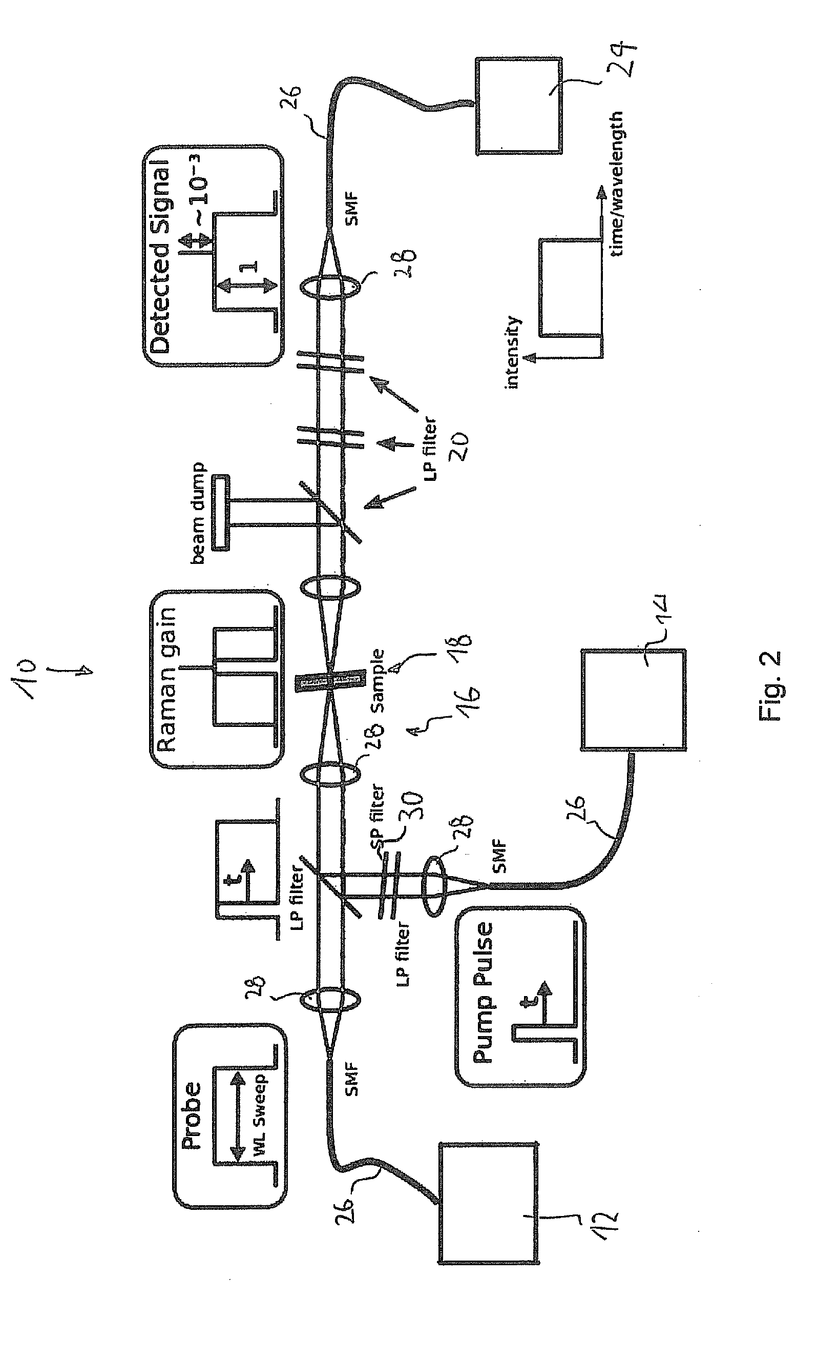
[0125]FIG. 2 is a schematic overview of a system 10 for stimulated Raman spectroscopy according to an embodiment of the present invention. The system 10 comprises a first light source 12 for generating a first light signal having a first wavelength and a second light source 14 for generating a second light signal having a second wavelength. In the present example...


PUM


Abstract

Disclosed herein is a system (10) for measuring light induced transmission or reflection changes, in particular due to stimulated Raman emission. The system comprises a first light source (12) for generating a first light signal having a first wavelength, a second light source (14) for generating a second light signal having a second wavelength, an optical assembly (16) for superposing said first and second light signals at a sample location (18), and a detection means (24) for detecting a transmitted or reflected light signal, in particular a stimulated Raman signal caused by a Raman-active medium when located at said sample location. Here in at least one of the first and second light sources (12, 14) is one or both of actively controllable to emit a time controlled light pattern or operated substantially in CW mode and provided with an extra cavity modulation means (64) for generating a time controlled light pattern. The detection means (24) is capable of recording said transmitted or reflected light signal, in particular stimulated Raman signal, as a function of time.

Description

FIELD OF THE INVENTION[0001]The present invention is in the field of optical spectroscopy. In particular, the invention relates to a system and method for measuring light induced transmission or reflection changes, in particular due to stimulated Raman emission.BACKGROUND OF THE INVENTION[0002]Raman spectroscopy is a well-established method to examine materials by investigating inelastic scattering of probe light. In 1928, C. V. Raman was the first who observed that intense light incident on a sample creates a wavelength shift due to inelastic scattering of light at phonons representing vibrational excitation modes of chemical bonds. The general concept of Raman scattering is explained with reference to the left half of FIG. 1. As indicated therein, an incident photon, also referred to as “pump photon” with a frequency ωpump is incident on a Raman active medium and gets annihilated. The medium which was in a quantum mechanical ground state before gets excited into a vibrational or r...

Claims


Application Information

Patent Timeline
IPC IPC(8): G01N21/65G01J3/44
CPCG01N21/65G01J3/4412G01N2201/0683G01N2201/06113G01N2201/0697G01J3/44H01S3/06758H01S3/09415H01S3/10015H01S3/1618H01S3/2391H01S3/302H01S3/0064H01S3/0078G01N2021/655H01S3/094069
Inventor HUBER, ROBERT, ALEXANDERKLEIN, THOMASWIESER, WOLFGANGKARPF, SEBASTIANEIBL, MATTHIAS
Owner MEDIZINISCHES LASERZENTRUM LUEBECK GMBH
Why Eureka
Try Eureka