
Dc-dc converter with configurable compensator

Inactive Publication Date: 2016-03-31
IDT EURO GMBH
View PDF2 Cites 1 Cited by
  • Summary
  • Abstract
  • Description
  • Claims
  • Application Information

AI Technical Summary

Benefits of technology

The present invention is a controller that can be easily designed for different power converters by selecting from a list of pre-made compensators or adjusting them based on a function using a digital communication bus. The invention also includes a method for determining, configuring, and storing the compensators, ensuring that suitable ones are used for a wide range of power converters. The technical effect of this invention is to simplify the design process and improve the performance of power converters.

Problems solved by technology

However, module end users may not have the required communication bus at their disposal or may not desire to utilise the GUI because of the complexity of such a task.
Adaptive controllers may be employed to obviate this need, but the frequency and phase characteristics of the final system after adaptive control compensation has converged can be unpredictable and therefore the response cannot be pre-determined to any suitable degree of certainty.
Typically, adaptive controllers perform poorly in this situation because the learning of the adaptive loop is disrupted by the mode changes
However, the requirement to design a robust controller that is stable over all power stage parameter values and conditions is at odds with the requirement to maximize regulation performance.
It is especially difficult in the case of DC-DC POL modules to determine and select a suitable compensator becausea) the output capacitance of the end user is typically not well defined when the module manufacturer determines the compensation andb) the end user has limited means or skill in determining and configuring the correct compensation once the output capacitance is well defined.

Method used


Image

  • Dc-dc converter with configurable compensator
  • Dc-dc converter with configurable compensator
  • Dc-dc converter with configurable compensator

Examples


Embodiment Construction

[0036]For the sake of example, the invention will be described in relation to the PID embodiment, although it will be clear that the same principles can be realised equivalently in any other embodiment. Let the proportional, integral and derivative gains be identified as Kp, Ki and Kd respectively.

[0037]Referring back to the buck converter of as shown in FIG. 1, it is well known to one skilled in the art that compensation of the controller should be performed for the most critical component and parameter values in order to guarantee stability of the converter under all conditions. The output bulk capacitance C, is often the component value or parameter that is known with least certainty, and therefore using this as an example, the compensation would be designed for the lowest value of capacitance expected in the converter.

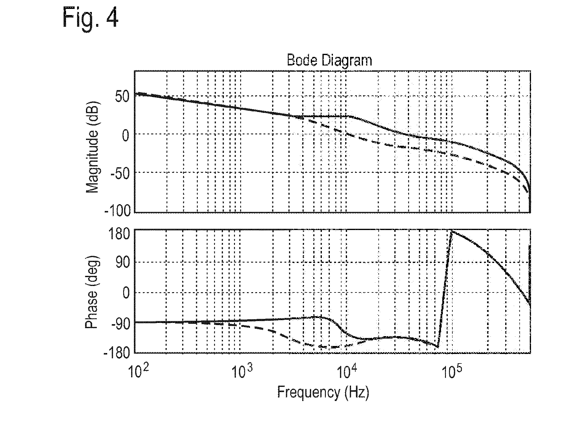
[0038]The Bode plot of the open loop gain of such a system is shown in FIG. 4 (full line). The dotted line of FIG. 4 shows that the loop response changes dramatica...


PUM


Abstract

A controller of a power converter and related method pre-determine a range of suitable compensators across an end user's design space and permit the end user to configure the compensator such that the most suitable compensator is selected.

Description

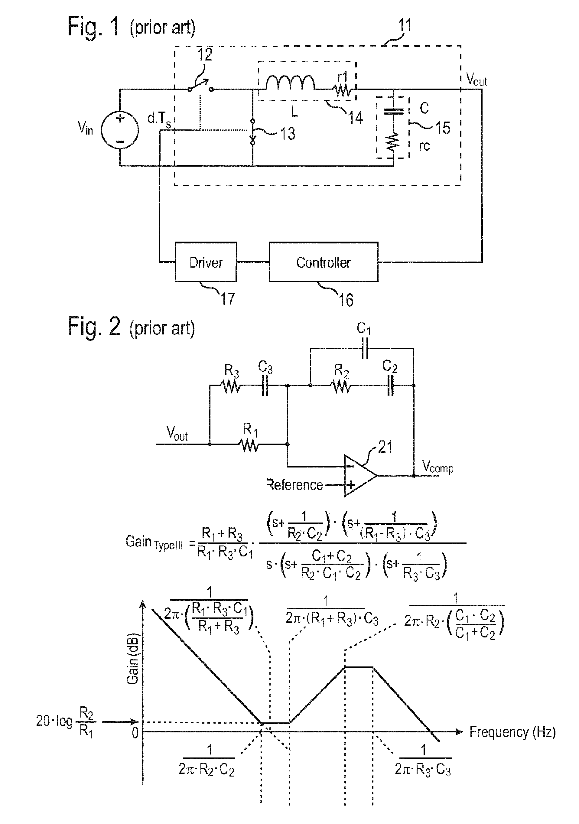
FIELD OF THE INVENTION[0001]The present disclosure relates to DC-DC conversion with configurable compensators and related method for the purpose of stability and regulation.BACKGROUND OF THE INVENTION[0002]In DC-DC conversion controllers are generally compensated for the purposes of stability and regulation.[0003]A typical DC-DC converter arrangement is shown in FIG. 1.[0004]The DC-DC converter arrangement comprises a switchable power stage 11, wherein an output voltage is generated according to a switching signal and an input voltage. The switching signal is generated in a digital controller 16 that adjusts the output voltage to a reference voltage. The driver 17 translates the switching signal to individual switching signals for the high-side switch 12 and the low side-side switch 13. The switchable power stage further comprises an inductor 14 shown in terms of inductance and equivalent series resistance and a capacitor 15 shown in terms of its capacitance and equivalent series re...

Claims


Application Information

Patent Timeline
IPC IPC(8): H02M3/04H02M1/00
CPCH02M3/04H02M3/156H02M3/157H02M1/0025
Inventor KELLY, ANTHONY
Owner IDT EURO GMBH
Learn More