Electronic control unit

a technology of electronic control unit and control circuit, which is applied in the direction of power supply for data processing, instruments, measurement devices, etc., can solve the problems of large capacity capacitors and increase the production cost of electronic control units, and achieve the effect of preventing the reset operation of the microcomputer and lowering the voltage of the power circui

Active Publication Date: 2016-04-07
DENSO CORP +1
View PDF16 Cites 13 Cited by
  • Summary
  • Abstract
  • Description
  • Claims
  • Application Information

AI Technical Summary

Benefits of technology

[0006]It is an object of the present disclosure to provide an electronic control unit that is capable of preventing the reset operation of the microcomputer at the time of switching of the microcomputer to a normal mode.
[0009]According to the above, the mode switcher is a different circuit from the microcomputer, and the mode switcher switches the power circuit to the normal mode prior to the switching of the microcomputer. Therefore, at the time of restarting of the microcomputer, the power circuit is already operating in the normal operation, capable of supplying the electric power required for the normal restart operation. Thus, the restart of the microcomputer prior to the mode switching of the power circuit is prevented, and the reset operation of the microcomputer due to the unstable power output (i.e., a lowered voltage of the power circuit) from the power circuit is prevented. Further, the reset operation of the microcomputer is prevented without using a large capacity capacitor.

Problems solved by technology

However, to prevent the restart of the microcomputer, a large capacity capacitor is required.
Therefore, the production cost of the electronic control unit may be increased when the preventive measure for the restart of the microcomputer is implemented.

Method used


Image

  • Electronic control unit
  • Electronic control unit
  • Electronic control unit

Examples


first embodiment

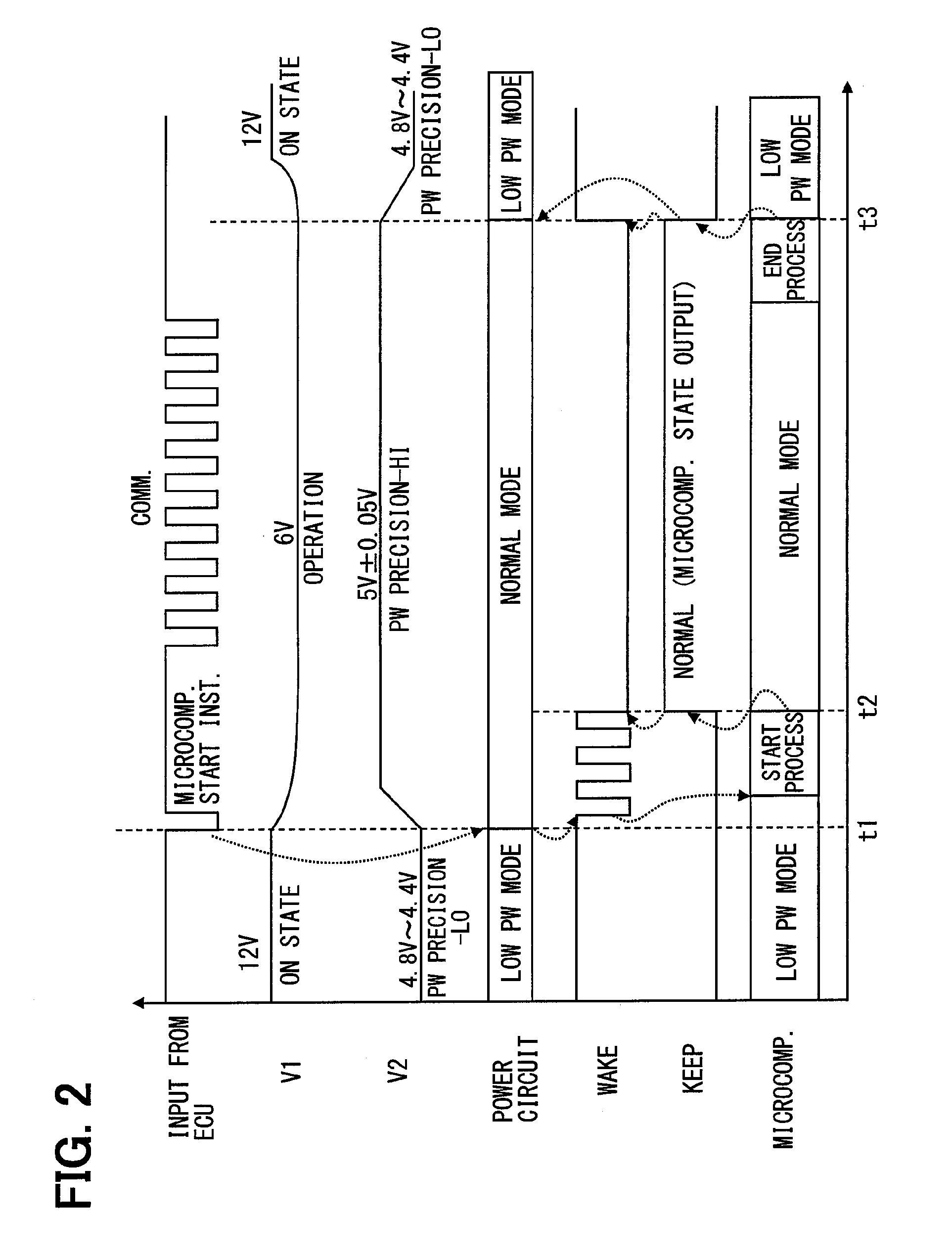
[0015]First, a configuration of an electronic control unit concerning the present embodiment is described with reference to FIGS. 1 and 2.

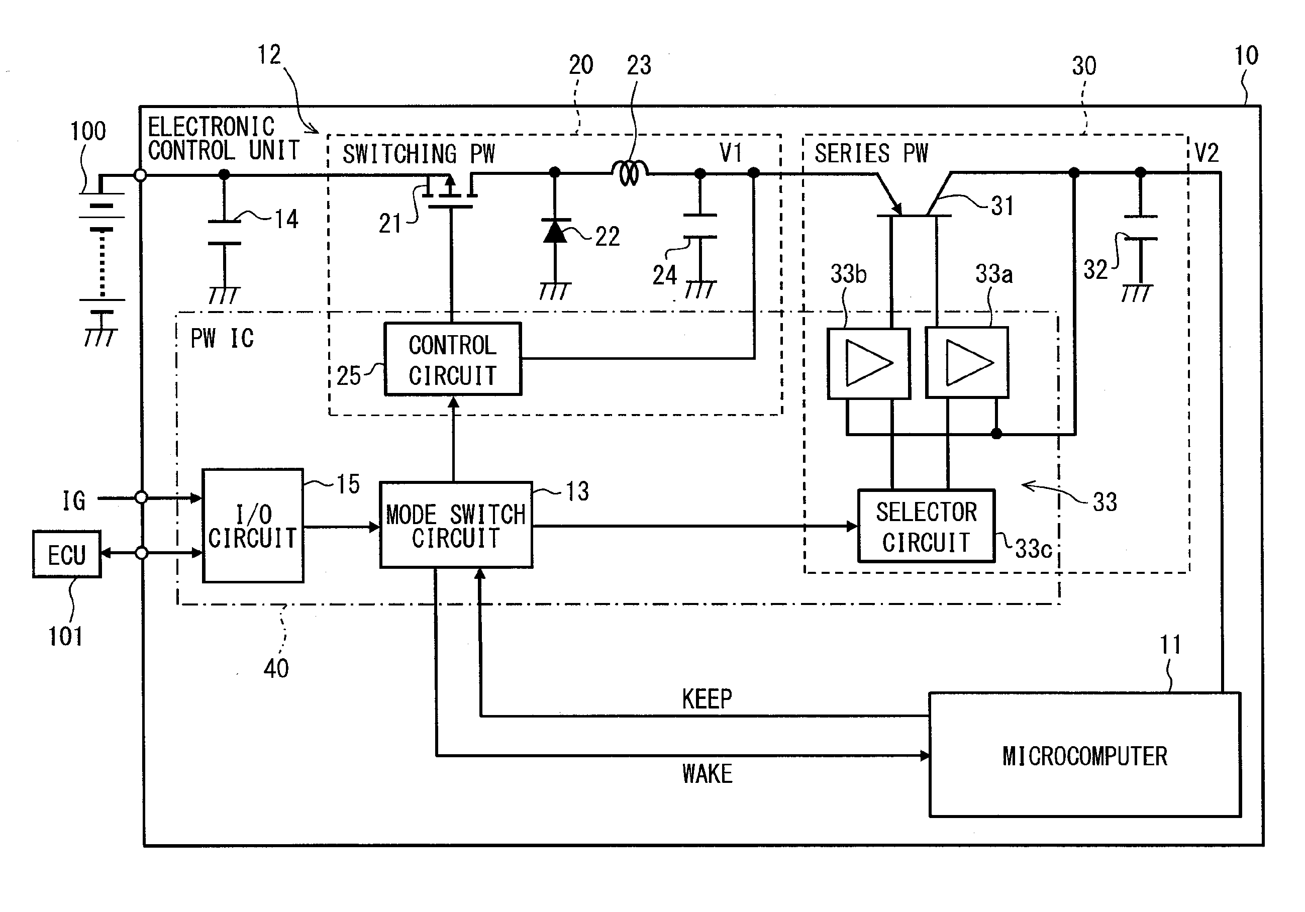
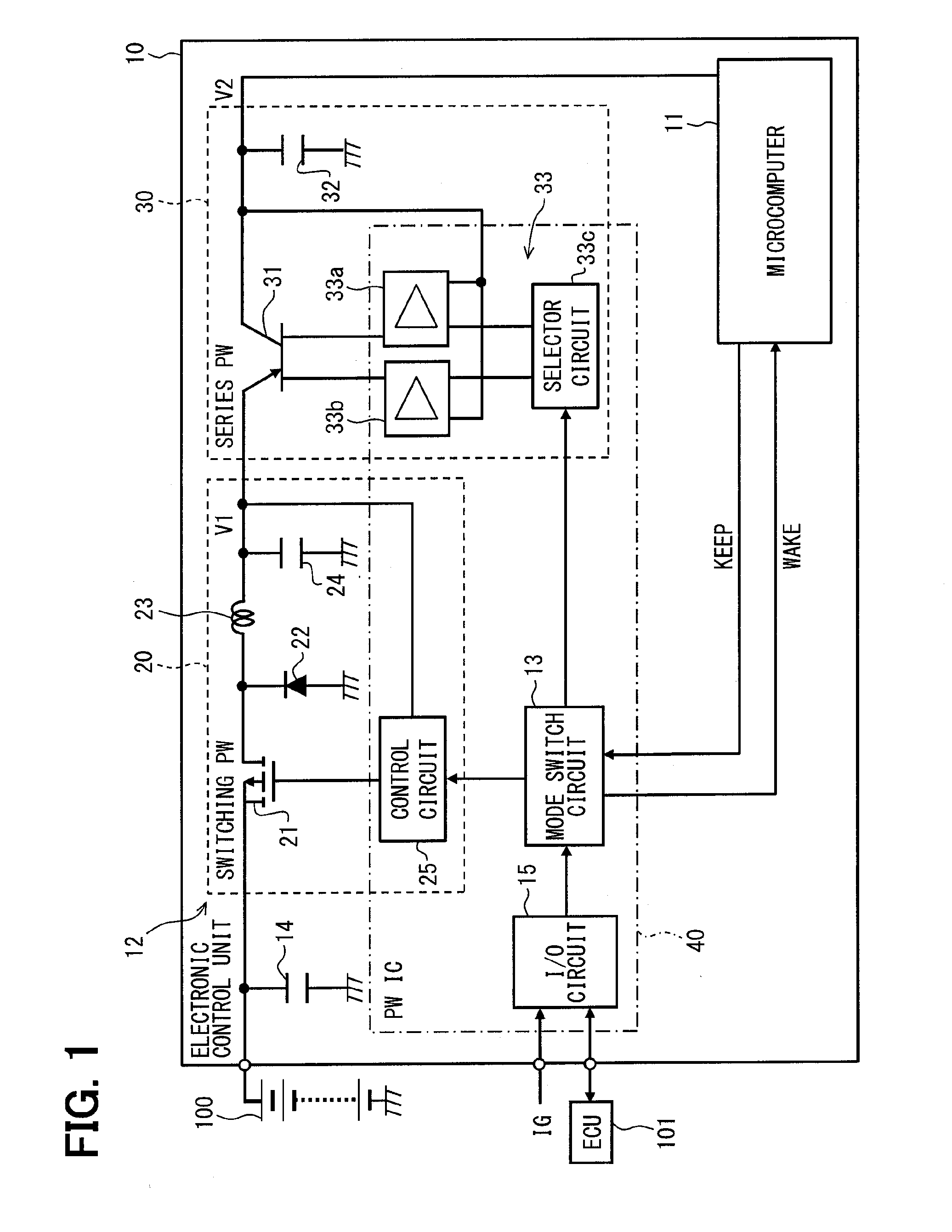
[0016]An electronic control unit 10 shown in FIG. 1 is disposed in a vehicle. The electronic control unit 10 is provided with a microcomputer 11, a power circuit 12, and a mode switch circuit 13. The electronic control unit 10 is further provided with a capacitor 14 and an input / output circuit 15.

[0017]The microcomputer 11 has components such as Central Processing Unit (CPU), Read Only Memory (ROM), Random-Access Memory (RAM), a register, an Input-Output (I / O) port, and the like. In the microcomputer 11, CPU performs signal processing according to various data etc. which are obtained via a bus as well as according to a control program that is pre-memorized in ROM with a help of a memory function of RAM or the register. The signal derived from the signal processing is outputted to the bus. Therefore, the microcomputer 11 performs the various functi...

second embodiment

[0075]In the present embodiment, the description is focused to a difference of the electronic control unit 10 in the preceding embodiment. FIG. 3 shows a portion of the electronic control unit 10 regarding a series power source concerning the present embodiment.

[0076]As shown in FIG. 3, the series power source 30 of the electronic control unit 10 has an excessive current detector circuit 50 that compares the electric current flowing through the second transistor 31 with a predetermined threshold value and detects the excessive electric current. The other configuration other than the above is the same as the first embodiment.

[0077]In the present embodiment, the first transistor 21 of the switching power source 20 is also put in the always-ON state, just like the first embodiment. The excessive current detector circuit 50 is formed as a part of the above-mentioned power IC 40.

[0078]The excessive current detector circuit 50 has a resistor 51, a differential amplifier 52, a comparator 5...


PUM


Abstract

An electronic control unit includes a microcomputer and a power circuit that supplies an electric power to the microcomputer. The microcomputer and the power circuit respectively operate in a normal operation mode and in a low power operation mode that consumes less power than the normal operation mode. The electronic control unit further includes a mode switcher for switching the operation modes of the microcomputer and the power circuit according to an input signal from an external device. When a mode switch signal for switching the operation mode of both devices to the normal operation mode, the mode switcher first switches the power circuit to the normal operation mode and subsequently switches the microcomputer to the normal operation mode, which prevents a reset operation of the microcomputer without using a large capacity capacitor.

Description

CROSS REFERENCE TO RELATED APPLICATION[0001]The present application is based on and claims the benefit of priority of Japanese Patent Application No. 2014-205683, filed on Oct. 6, 2014, the disclosure of which is incorporated herein by reference.TECHNICAL FIELD[0002]The present disclosure generally relates to an electronic control unit including a microcomputer and a power circuit respectively having two operation modes (i.e., a normal mode and a low power consumption mode).BACKGROUND INFORMATION[0003]A Japanese Patent Laid-Open No. 2009-184423 (patent document 1) described below discloses an electronic control unit, which includes a microcomputer having a normal mode (i.e., a normal operation mode) and a low power consumption mode (i.e., a standby mode) as two operation modes and a power circuit having a normal mode (i.e., a normal electric current mode) and a low power consumption mode (i.e., a low electric current mode) as two operation modes.[0004]According to the patent documen...

Claims


Application Information

Patent Timeline
Patent Type & Authority Applications(United States)
IPC IPC(8): G06F1/26G06F1/32
CPCG06F1/3243G06F1/26G06F1/3209
Inventor ITOU, AKITOMAEDA, NAOKITSUDA, MASAYUKIYOKOYAMA, ATSUKO
Owner DENSO CORP
Why Eureka
Try Eureka