Resonator, oscillator, electronic apparatus, and mobile object

a technology of oscillator and oscillator, which is applied in the direction of piezoelectric/electrostrictive/magnetostrictive devices, electrical apparatus, piezoelectric/electrostriction/magnetostriction machines, etc., can solve the problems of deteriorating the equivalent series resistance value of the piezoelectric device, increasing the thickness, and leaking vibration energy toward the base. achieve the effect of high reliability

Active Publication Date: 2016-04-07
SEIKO EPSON CORP
View PDF4 Cites 4 Cited by
  • Summary
  • Abstract
  • Description
  • Claims
  • Application Information

AI Technical Summary

Benefits of technology

[0029]According to this application example, since the resonator low in CI value (the equivalent series resistance value) and small in frequency variation in the high-temperature atmosphere and the low-temperature atmosphere is provided, there is an advantage that the mobile object high in reliability can be configured.

Problems solved by technology

Therefore, the leakage of the vibration energy toward the base increases due to the decrease in distance between the vibrating region and the bonding material.
Therefore, there has been a problem that the equivalent series resistance value of the piezoelectric device is deteriorated.
Further, if S1 / S2 is set to be equal to or larger than 1, it becomes unachievable to shorten the distance S1 between the two first bonding members for supporting the resonator element, and thus, it becomes unachievable to decrease the amount of each of the two first bonding members of the resonator element gradually increasing in thickness from the outer edge toward the center, and therefore, the distance between the vibrating region and the first bonding members is shortened, and thus, there occurs a possibility that the leakage of the vibration energy toward the base increases, or the distortion caused in the resonator element by the mounting stress is increased.

Method used


Image

  • Resonator, oscillator, electronic apparatus, and mobile object
  • Resonator, oscillator, electronic apparatus, and mobile object
  • Resonator, oscillator, electronic apparatus, and mobile object

Examples


Embodiment Construction

[0042]Some embodiments of the invention will hereinafter be explained in detail based on the accompanying drawings. It should be noted that in the drawings described hereinafter, the dimensions and the ratios of the constituents are arbitrarily made different from those of the actual constituents in some cases in order to provide the constituents with recognizable sizes in the drawings.

Resonator

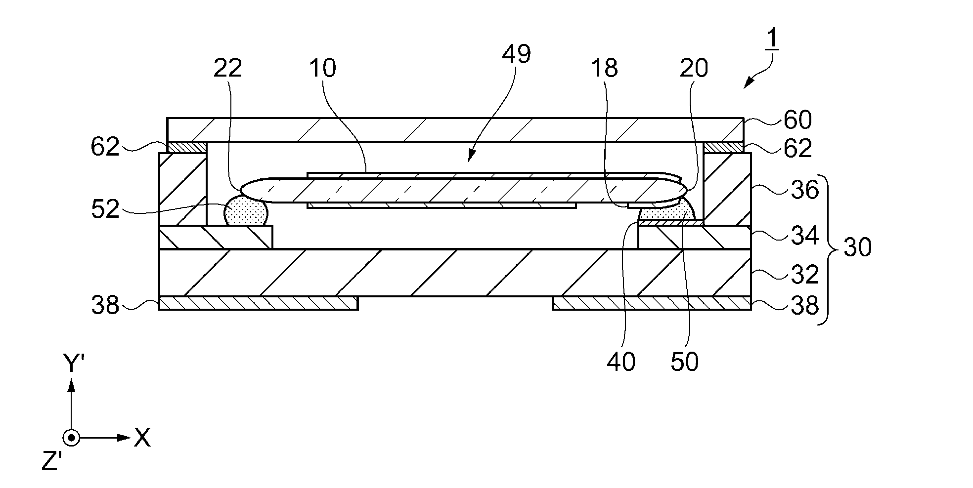
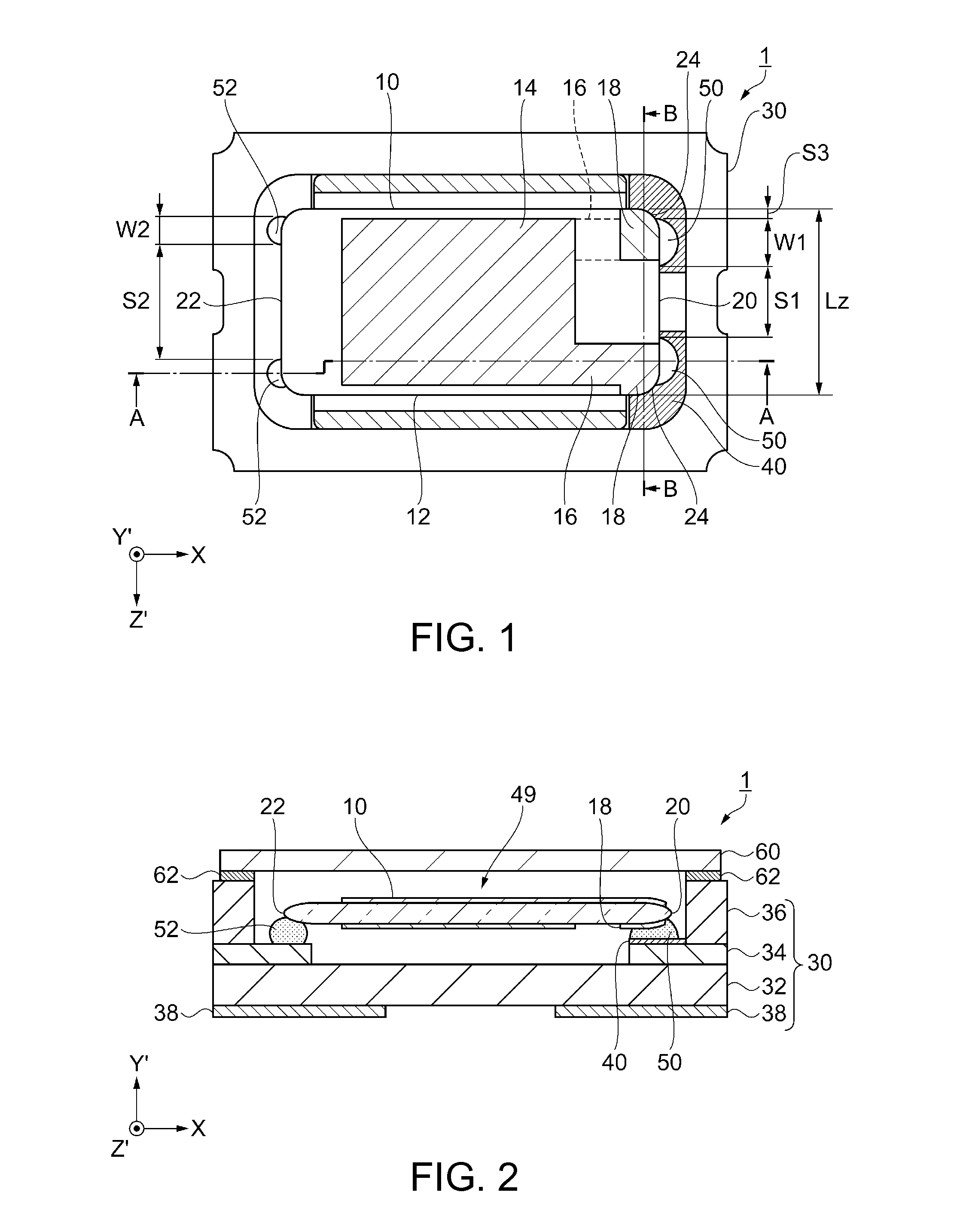
[0043]Firstly, as an example of the resonator according to the embodiment of the invention, there is cited an AT-cut quartz crystal resonator provided with an AT-cut quartz crystal element having a thickness-shear vibration mode as a principal vibration mode, and a general configuration of the AT-cut quartz crystal resonator will be explained with reference to FIGS. 1, 2, and 3.

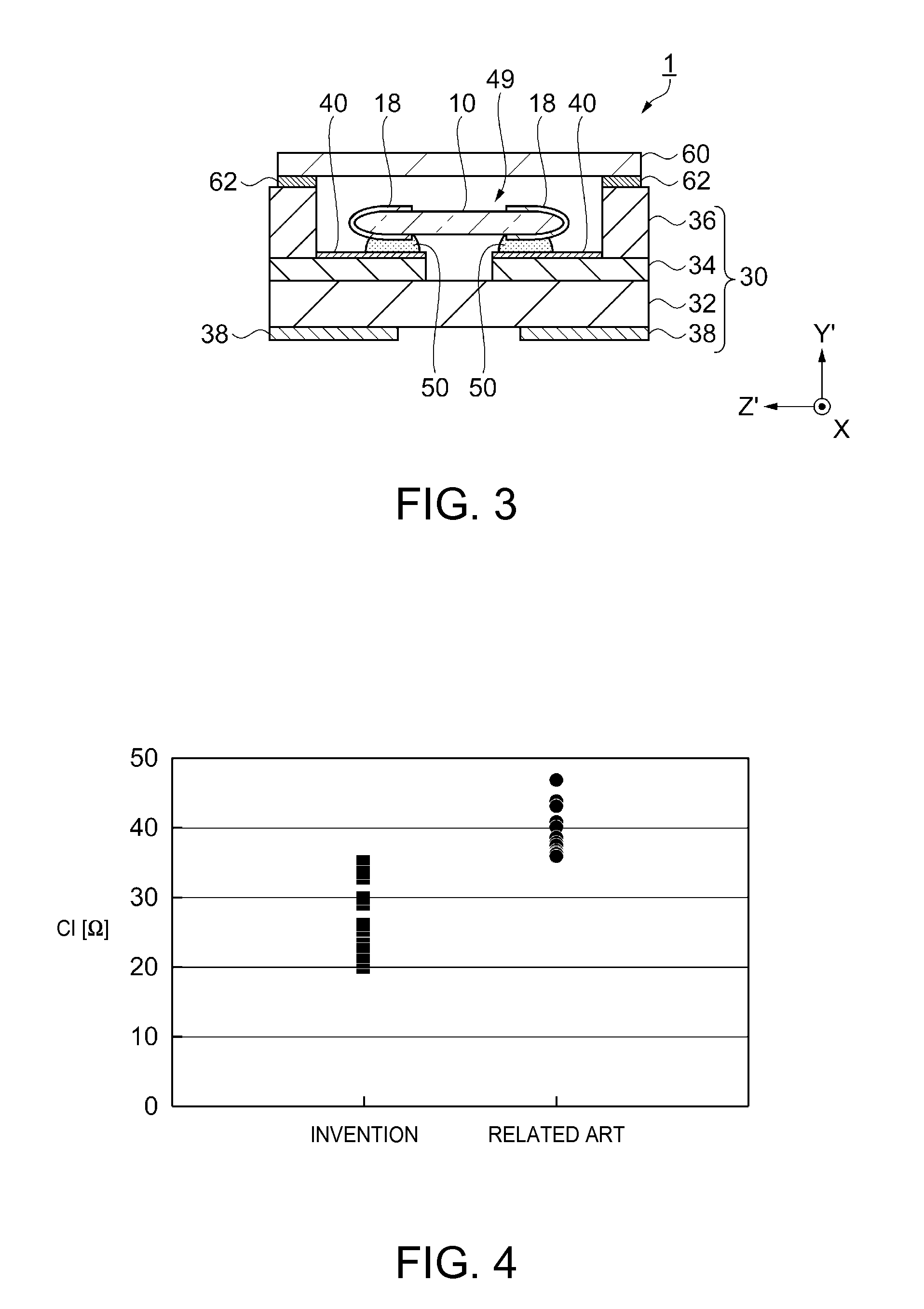
[0044]FIG. 1 is a schematic plan view showing a structure of the resonator according to the embodiment of the invention. FIG. 2 is a cross-sectional view along the A-A line in FIG. 1. FIG. 3 is a schematic cross-sectio...


PUM


Abstract

A resonator includes a resonator element including a substrate gradually increasing in thickness from an outer edge toward a center, excitation electrodes respectively disposed on both principal surfaces of the substrate, and a pair of electrode pads electrically connected to the excitation electrodes, disposed on at least one of the both principal surfaces, and disposed on one end side of the substrate, and a second substrate as a base, the pair of electrode pads are bonded to the second substrate via respective first bonding members, two places of the other end of the substrate on the opposite side to the one end are bonded to the second substrate via respective second bonding members, and a distance S1 between the two first bonding members, and a distance S2 between the two second bonding members fulfill S1<S2.

Description

BACKGROUND[0001]1. Technical Field[0002]The present invention relates to a resonator, and an oscillator, an electronic apparatus, and a mobile object each equipped with the resonator.[0003]2. Related Art[0004]A quartz crystal resonator, in which a quartz crystal resonator element vibrating in a thickness-shear vibration mode as a vibration mode of the principal vibration is used, is suitable for miniaturization and higher frequency, and is superior in a frequency-temperature characteristic, and is therefore used in a variety of fields such as an oscillator and electronic equipment. In particular, in recent years, there have been used quartz crystal resonators each functioning as a reference clock in order to control an electronic control unit (ECU) such as an antilock brake system (ABS), a tire pressure monitoring system (TPMS), an engine control system, or a vehicle attitude control system installed in a vehicle.[0005]Such quartz crystal resonators are each formed by mounting a qua...

Claims


Application Information

Patent Timeline
Patent Type & Authority Applications(United States)
IPC IPC(8): H01L41/053H03H9/17
CPCH03H9/17H01L41/053H03H9/02102H03H9/0514H03H9/0542H03H9/1014
Inventor MATSUGI, KIYOTAKAFUNATSU, KAZUKI
Owner SEIKO EPSON CORP
Why Eureka
Try Eureka