Endovascular Treatment Apparatus and Method

Inactive Publication Date: 2016-04-21
ANGIODYNAMICS INC
View PDF3 Cites 3 Cited by
  • Summary
  • Abstract
  • Description
  • Claims
  • Application Information

AI Technical Summary

Benefits of technology

The present invention provides an improved sheath device for use with thermal treatment devices in blood vessels. The device has several technical effects. Firstly, it is made of a translucent material to improve visibility during insertion and withdrawal. Secondly, the device has an ultrasonically visible reinforcement element along its wall which acts as a guide for needle punctures and protection against damage during tumescent injections. Thirdly, the device includes distance marks on its longitudinal tube to easily determine the insertion depth and adjust the sheath position during the procedure. Lastly, the adjustable depth stop feature on the sheath shaft allows for easy positioning and retention during the procedure. Overall, this sheath device provides improved visibility, protection, and ease of use during thermal treatment procedures in blood vessels.

Problems solved by technology

When the valves are malfunctioning or only partially functioning, however, they no longer prevent the back-flow of blood into the superficial veins.
Symptoms of reflux include varicose veins and other cosmetic deformities, as well as aching, itching, and swelling of the legs.
If left untreated, venous reflux may cause severe medical complications such as bleeding, phlebitis, ulcerations, thrombi and lipodermatosclerosis.
Current art sheath tips are often difficult to clearly visualize under either ultrasonic guidance or fluoroscopic imaging.
One problem with the use of a conventional sheath is that the sheath material often blocks the red aiming beam from being clearly visible on the skin surface as the fiber is advanced through the sheath.
Again, visualization of the target perivenous space is often difficult, and the user may inadvertently puncture the sheath wall with the needle tip during placement.
The delicate fiber may also be damaged by incorrect placement of the needle.
The energy reacts with the blood remaining in the vessel and causes heat, which damages the vein wall which, in turn, causes cell necrosis and eventual vein collapse.
One problem is the difficulty in visualizing the sheath and particularly the tip as it is positioned just proximal to the sapheno-femoral junction.
Although some currently available sheaths may be visible under fluoroscopic guidance, these same sheaths are not optimized for use with ultrasonic imaging modalities.
Incorrect placement may result in either incomplete occlusion of the vein or non-targeted thermal energy delivery to the femoral vein, which may result in deep vein thrombosis and its associated complications including pulmonary embolism.
Another possible complication of a misplaced device is possible vessel perforation.
Another problem with conventional sheaths is that they have shaft colorant.
The colorant results in difficulty visualizing the red aiming beam on the skin surface due to partial or complete blocking of the beam by the colored material.
In addition, most prior art sheaths do not provide a simple, easy mechanism for determining the rate at which the sheath / optical fiber assembly should be withdrawn through the vein during the actual treatment step.

Method used


Image

  • Endovascular Treatment Apparatus and Method
  • Endovascular Treatment Apparatus and Method
  • Endovascular Treatment Apparatus and Method

Examples


Embodiment Construction

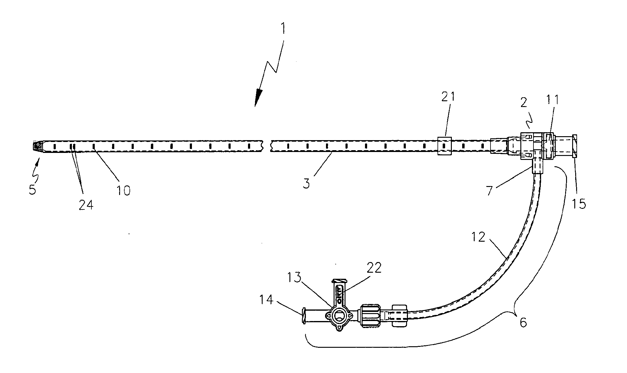
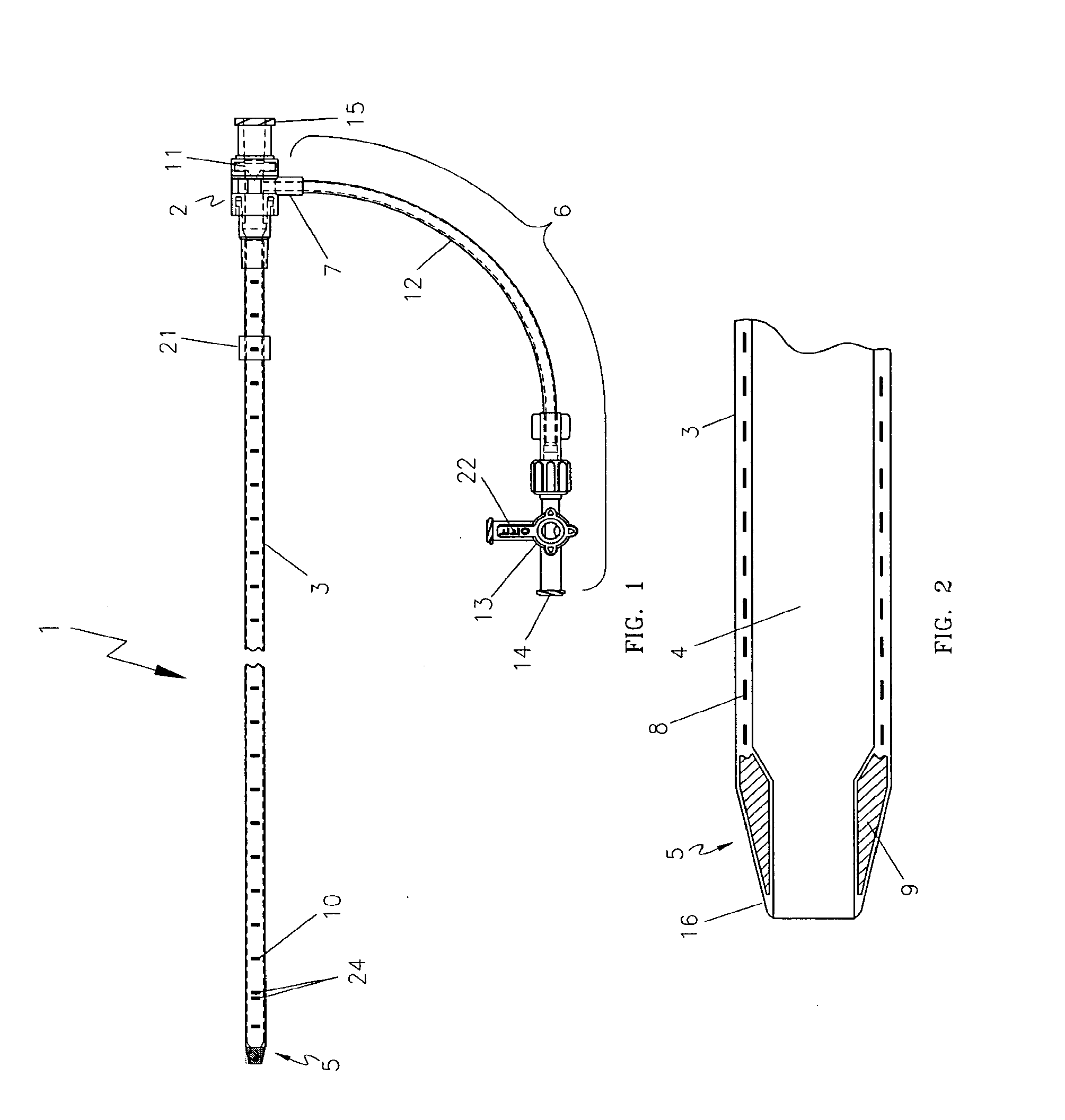
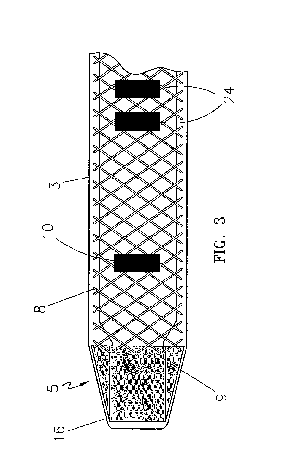
[0031]One embodiment of the present invention is shown in FIG. 1 through FIG. 3. The endovascular laser treatment sheath 1 is comprised of a hub 2, shaft 3 with through lumen 4, and distal tip 5. The hub 2 may include a side arm assembly 6 for infusion or aspiration of fluids during the thermal treatment procedure. The sheath shaft 3 is comprised of a visibly translucent material reinforced with a wire 8 having a predefined pattern such as braided or coil-wound pattern which is embedded within the translucent material, as shown in FIG. 3. The outer wall of the sheath shaft 3 may include distance markers 10. An adjustable depth stop 21 is coaxially and slidably arranged around the sheath shaft 3.

[0032]The sheath tip 5 has a tapered outer profile as shown in FIG. 2 and FIG. 3. As is well known in the art, the taper provides a smooth transition from the outer diameter of the sheath shaft 3 to the smaller outer diameter of the sheath distal tip. The taper aids in insertion and advanceme...


PUM


Abstract

An endovascular sheath device for use with a thermal treatment apparatus is provided. The device includes a longitudinal tube which is designed to receive a thermal treatment device and is designed to be inserted into a blood vessel. An ultrasonically visible reinforcement element is disposed along the length of the longitudinal tube. The reinforcement element such as a braided wire provides several functions including increased visibility under ultrasound, clearer identification of sheath tip, and increased durability to protect the fiber from needle punctures during tumescent injections into the perivenous space. The wire reinforcement also increases shaft torquability and kink resistance during sheath insertion and withdrawal.

Description

CROSS REFERENCE TO RELATED APPLICATIONS[0001]This application claims priority to U.S. provisional application No. 60 / 516,156, filed Oct. 31, 2003, which is incorporated into the present specification by reference.FIELD OF THE INVENTION[0002]The present invention relates to a medical device apparatus and method for treatment of blood vessels. More particularly, the present invention relates to an endovascular sheath apparatus and method for minimally invasive treatment of venous reflux disease.BACKGROUND OF THE INVENTION[0003]Veins can be broadly divided into three categories: the deep veins, which are the primary conduit for blood return to the heart; the superficial veins, which parallel the deep veins and function as a channel for blood passing from superficial structures to the deep system; and topical or cutaneous veins, which carry blood from the end organs (e.g., skin) to the superficial system. Veins are thin-walled and contain one-way valves that control blood flow. Normally...

Claims


Application Information

Patent Timeline
IPC IPC(8): A61B18/18A61B18/04
CPCA61B18/18A61B2018/00345A61B18/04A61B18/22A61B2018/00404A61B2218/002A61B2218/007A61B2090/3983A61B2090/3925A61B2090/3966A61B2018/2285
Inventor APPLING, WILLIAM M.
Owner ANGIODYNAMICS INC
Why Eureka
Try Eureka