Aluminum deposition devices and their use in spot electroplating of aluminum

a technology of aluminum deposition device and spot electroplating, which is applied in the direction of contact device, electrolysis component, electrolysis process, etc., can solve the problems of inefficiency of aqueous electroplating, voc emissions, and inability to electrodepose aluminum nor its alloys from aqueous solutions

Inactive Publication Date: 2016-04-21
UT BATTELLE LLC +1
View PDF13 Cites 23 Cited by
  • Summary
  • Abstract
  • Description
  • Claims
  • Application Information

AI Technical Summary

Benefits of technology

[0008]In the electroplating method, the electrolyte is made to be in contact with an anode in the device at the time the electrolyte is released from the protective device and applied as a coating on the substrate. A voltage potential is then applied between the anode and the substrate (polarized as cathode) in order to produce a coating of aluminum within an area bounded by the coating of the electrolyte. A further advantage of the methods described herein is the ability to spot electroplate metallic substrates that are generally too large or cumbersome to electroplate by immersing or dipping into a bath.

Problems solved by technology

Unfortunately, neither aluminum nor its alloys can be electrodeposited from aqueous solutions because hydrogen is evolved before aluminum can be plated.
Not surprisingly, the technique raises a number of environmental and safety objections because the alkyl aluminum compounds are pyrophoric and toxic, and the toluene solvent is flammable and can lead to volatile organic compound (VOC) emissions.
The inefficiency of aqueous electroplating also makes it a major energy consumer.
Therefore, they are amenable for the electroplating of reactive elements, which is impossible using aqueous or other organic solvents.
However, because of the hygroscopic nature of AlCl3 and the resulting chloroaluminate, the electroplating generally must be performed in an inert gas atmosphere, which significantly increases cost and complexity of the process.

Method used


Image

  • Aluminum deposition devices and their use in spot electroplating of aluminum
  • Aluminum deposition devices and their use in spot electroplating of aluminum
  • Aluminum deposition devices and their use in spot electroplating of aluminum

Examples


examples

Introduction

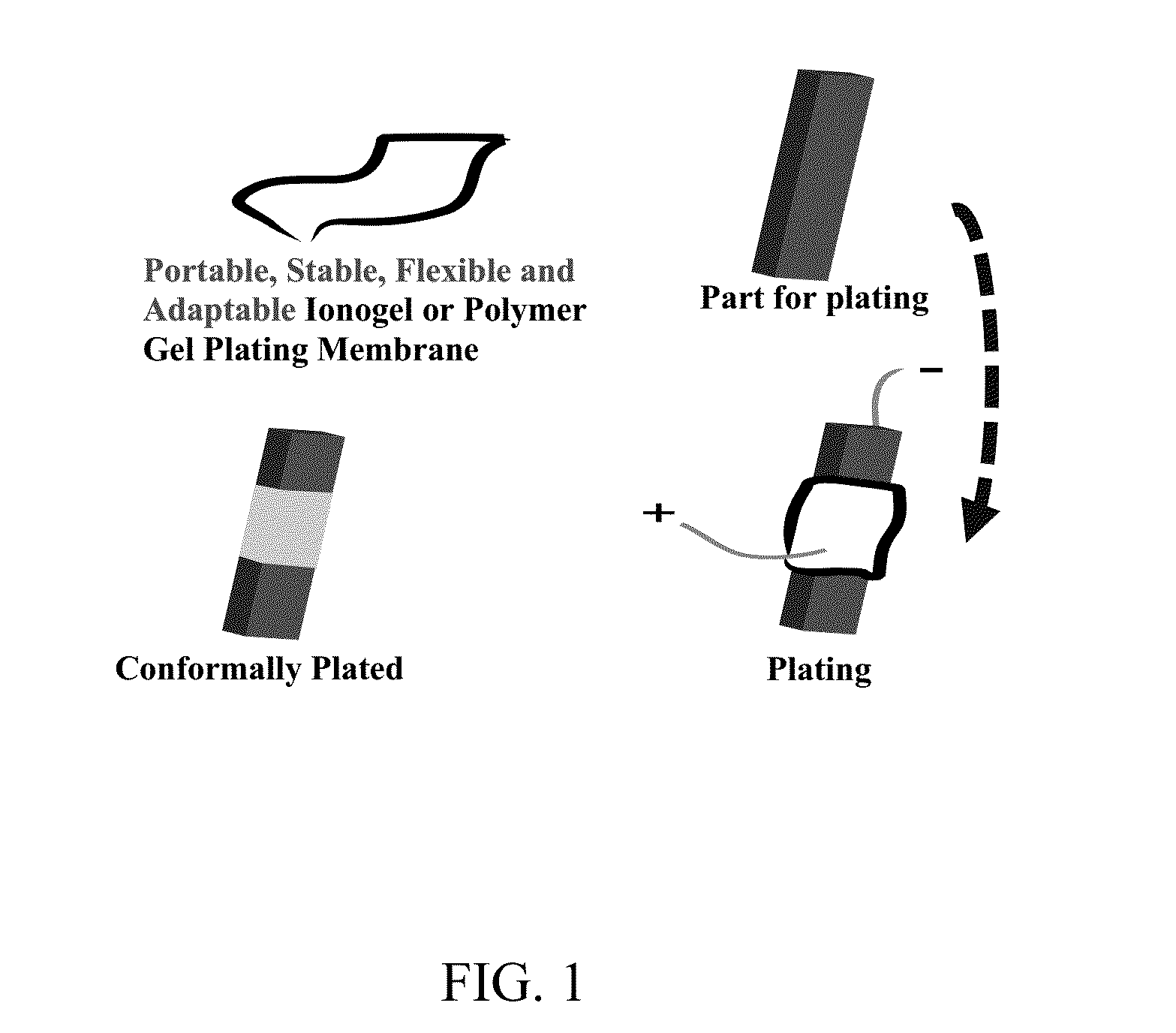
[0060]By one methodology, the moisture sensitivity of chloroaluminate-based ionic liquids was significantly reduced by forming polymer gel electrolytes (polymer membranes), either by impregnating liquid electrolytes into preformed membranes, or by co-casting polymer and liquid electrolytes, or by copolymerization of monomers in the presence of plasticizers. For more practical applications, the polymer gel membranes can be cast directly onto aluminum foil, and the resulting layered composite wrapped around a substrate to perform the plating. In this configuration, the aluminum foil serves as the anode and the substrate as the cathode during the electroplating process. A general depiction of the process using a polymer gel electrolyte is provided in FIG. 1.

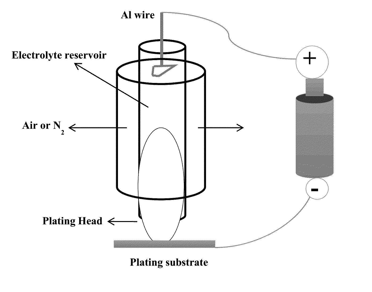
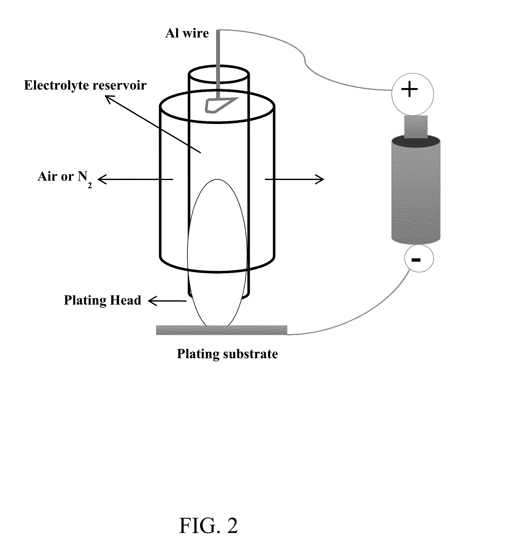
[0061]By another methodology, the moisture sensitivity of the chloroaluminate-based ionic liquids was significantly reduced by sealing the ionic liquid electrolyte inside the reservoir of a portable plating brush. The de...


PUM


Abstract

A method for spot electroplating aluminum onto a metallic substrate without submersion or dipping of the metallic substrate in an electroplating bath, the method comprising: (i) spot coating said metallic substrate with an aluminum ion-containing electrolyte contained within a protective structure possessing at least one aperture, and releasing said electrolyte from said at least one aperture onto said metallic substrate to form a coating of said electrolyte thereon, wherein said electrolyte is in contact with an anode; and (ii) applying a voltage potential between the anode and metallic substrate polarized as cathode when the aluminum ion-containing electrolyte is released from said aperture and forms a coating on the metallic substrate, to produce a coating of aluminum on the substrate. Devices, such as brush and ball pen plating devices, for achieving the above-described method are also described.

Description

[0001]This invention was made with government support under Prime Contract No. DE-AC05-00OR22725 awarded by the U.S. Department of Energy. The government has certain rights in the invention.FIELD OF THE INVENTION[0002]The present invention relates generally to methods and aluminum-containing electrolytes useful in the electroplating of aluminum, and more particularly, to devices useful in spot plating aluminum onto various metallic substrates.BACKGROUND OF THE INVENTION[0003]Metal surface coating has played an important role in extending the life cycle of structural materials commonly used in large rugged equipment for use on land, air, and sea. Aluminum and its many versatile alloys are routinely used as surface coatings for the corrosion protection of many metals, offering both barrier and sacrificial protection. In addition, aluminum and its alloys are being considered as favorable alternatives for cadmium coatings on the protective shells of electrical connectors in military gro...

Claims


Application Information

Patent Timeline
Patent Type & Authority Applications(United States)
IPC IPC(8): C25D5/02C25D17/00C25D3/44C25D5/06C25D5/04
CPCC25D5/02C25D5/06C25D17/005C25D3/44C25D5/04C25D3/665C25D17/14
Inventor DAI, SHENGSUN, XIAO-GUANGHUSSEY, CHARLES L.CHOU, LI-HSIEN
Owner UT BATTELLE LLC
Why Eureka
Try Eureka