Vertical hall sensors with reduced offset error

a technology of offset error and vertical hall sensor, which is applied in the field can solve the problems of not providing electrical symmetry, affecting the accuracy of vertical hall sensor, and relatively high offset voltage, and achieves the effect of increasing electrical symmetry and higher conductivity

Active Publication Date: 2016-04-21
MELEXIS TECH NV +1
View PDF4 Cites 10 Cited by
  • Summary
  • Abstract
  • Description
  • Claims
  • Application Information

AI Technical Summary

Benefits of technology

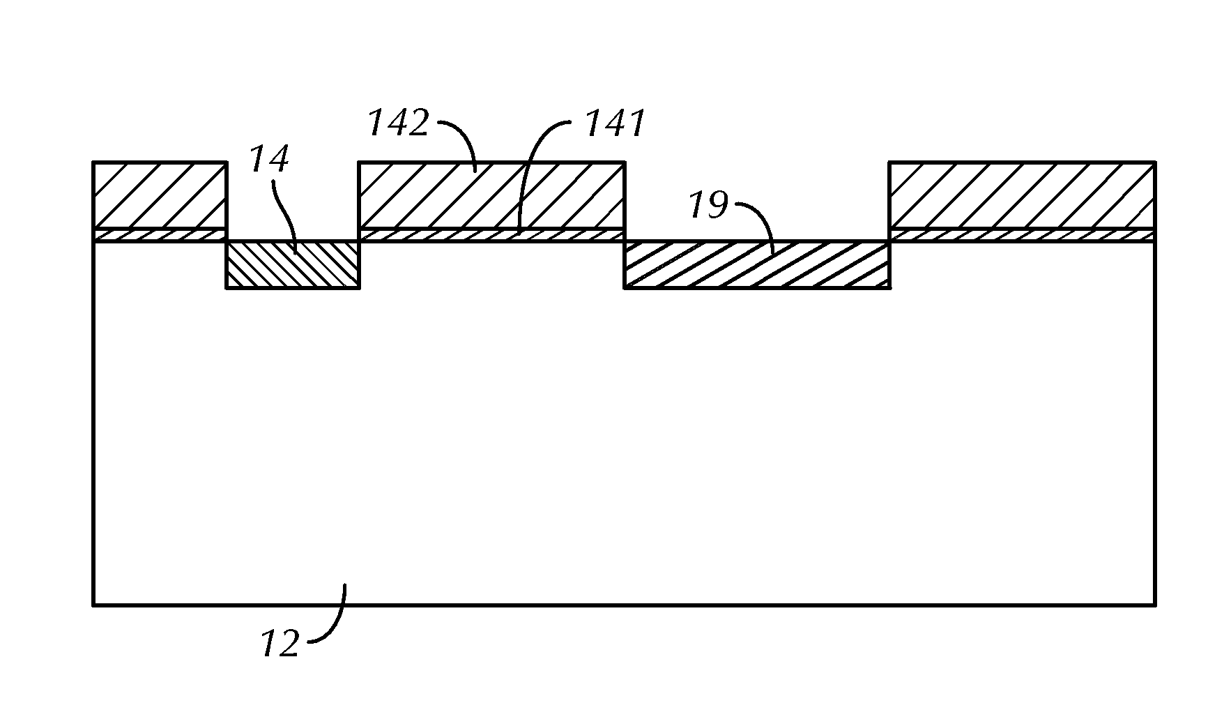
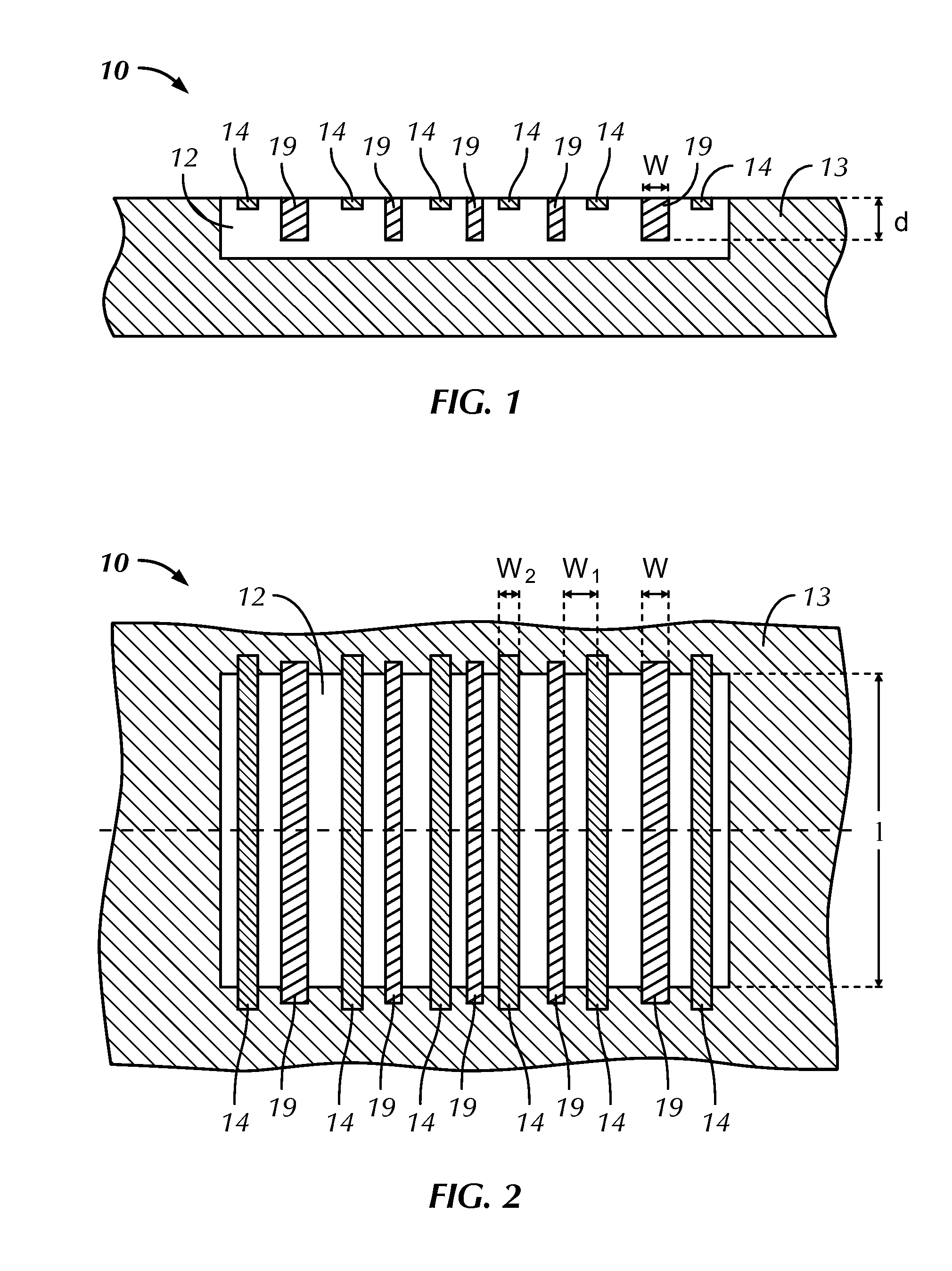
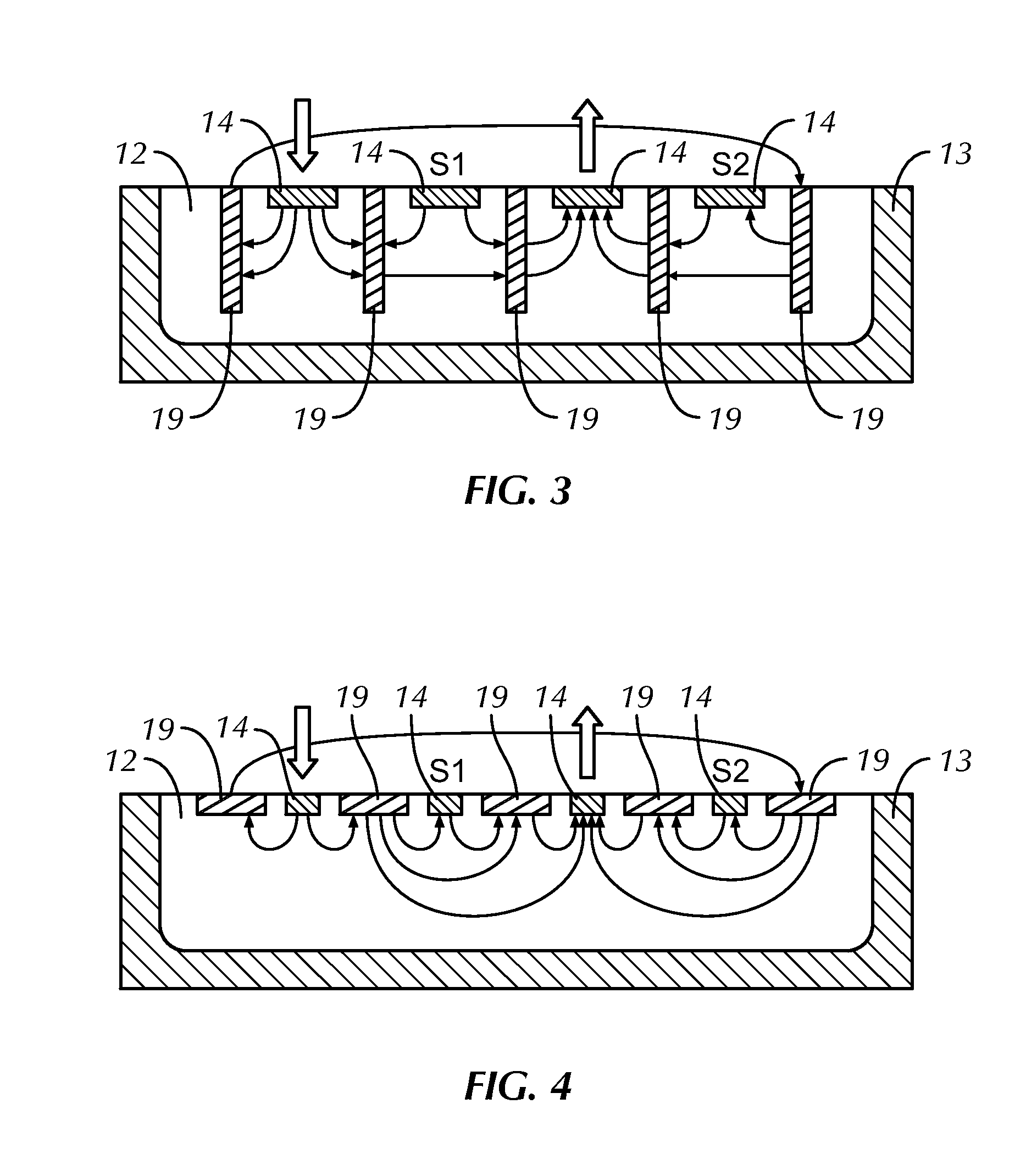
[0021]It is an advantage of embodiments of the present invention that the buffer regions extend so deep into the electrically conductive well that a majority of the currents, for instance more than 90% of the currents, such as all currents, between the well contacts go through the buffer regions.
[0022]In embodiments of the present invention, the buffer regions may have a width between the width of the well contacts and twice the depth of the electrically conductive well. The buffer regions may for example be between 6 and 20 times wider than the well contacts. It is an advantage of embodiments of the present invention that the buffer regions are so wide that all currents between the well contacts go through the buffer regions.
[0023]In embodiments of the present invention, the buffer regions neighboring the outer well contacts may form one entire buffer region surrounding the outer well contact. It is an advantage of embodiments of the present invention that the electrical symmetry is increased when the outer well contacts are embedded in buffer regions.
[0024]In a semiconductor chip according to embodiments of the

Problems solved by technology

They have, however, the disadvantage that they suffer from a relatively high offset voltage compared to horizontal Hall sensors.
A vertical Hall element, however, does not provide this electrical symmetry by default since all contacts are on one side and since the active area (e.g. an n-well) only has a limited depth.
This requires a time cons

Method used


Image

  • Vertical hall sensors with reduced offset error
  • Vertical hall sensors with reduced offset error
  • Vertical hall sensors with reduced offset error

Examples


Embodiment Construction

[0049]The present invention will be described with respect to particular embodiments and with reference to certain drawings but the invention is not limited thereto but only by the claims. The drawings described are only schematic and are non-limiting. In the drawings, the size of some of the elements may be exaggerated and not drawn on scale for illustrative purposes. The dimensions and the relative dimensions do not correspond to actual reductions to practice of the invention.

[0050]The terms first, second and the like in the description and in the claims, are used for distinguishing between similar elements and not necessarily for describing a sequence, either temporally, spatially, in ranking or in any other manner. It is to be understood that the terms so used are interchangeable under appropriate circumstances and that the embodiments of the invention described herein are capable of operation in other sequences than described or illustrated herein.

[0051]Moreover, the terms top,...


PUM


Abstract

A semiconductor chip for measuring a magnetic field based on the Hall effect. The semiconductor chip comprises an electrically conductive well having a first conductivity type, in a substrate having a second conductivity type. The semiconductor chip comprises at least four well contacts arranged at the surface of the well, and having the first conductivity type. The semiconductor chip comprises a plurality of buffer regions interleaved with the well contacts and having the first conductivity type. The buffer regions are highly conductive and the buffer region dimensions are such that at least part of the current from a well contact transits through one of its neighboring buffer regions.

Description

FIELD OF THE INVENTION[0001]The present invention relates to the field of vertical Hall sensors. More specifically, it relates to a system with limited, e.g. reduced, offset error for measuring a magnetic field and to a method for manufacturing such system.BACKGROUND OF THE INVENTION[0002]Vertical Hall sensors have the advantage that they can be manufactured using conventional semiconductor technology (e.g. CMOS). They have, however, the disadvantage that they suffer from a relatively high offset voltage compared to horizontal Hall sensors. The offset voltage is the voltage measured when no magnetic field is present.[0003]The measurement error due to offset voltage can be decreased by several techniques, such as for instance the spinning current technique. In this technique, the supply and readout contacts are cyclically interchanged. In one phase the offset is then added to the magnetic signal with positive sign and in the other phase with negative sign. By averaging both phases, t...

Claims


Application Information

Patent Timeline
IPC IPC(8): H01L43/06H01L43/14G01R33/07H01L43/04
CPCH01L43/065G01R33/077H01L43/14H01L43/04G01R33/07H10N52/01H10N52/101G01R33/0052H10N52/80
Inventor SCHOTT, CHRISTIANHOFMANN, PETER
Owner MELEXIS TECH NV
Why Eureka
Try Eureka