

Fast charging method for battery
a battery and fast charging technology, applied in the field of batteries, can solve the problems of increasing the cost of batteries, increasing the complexity of related technologies, and affecting the safety of batteries, and achieve the effect of improving the charging safety performance of batteries
- Summary
- Abstract
- Description
- Claims
- Application Information
AI Technical Summary
Benefits of technology
Problems solved by technology
Method used
Image

Examples
example 1
[0027]The battery was prepared by the technology of assembling a cathode, an anode, a separator, an electrolyte and a packaging shell, and then dealing with a formation process, an aging process and the like. The cathode was produced by coating a conductive film on surface of 12 μm aluminum foil (used as a conductive collector), and the conductive film contained 96.7 wt % LiCoO2, 1.7 wt % PVDF (used as a binder) and 1.6 wt % SP (used as a conductive additive). The anode was produced by coating a conductive film on surface of 8 μm copper foil (used as a conductive collector), and the conductive film contained 98% artificial graphite, 1.0% SBR (used as binder) and 1.0% CMC (used as thickening agent). The separator was a composite membrane of PP / PE / PP. The electrolyte was consisted of an organic solvent (30% EC+30% PC+40% DEC), LiPF6 and an additive (0.5 wt % VC+5 wt % FEC+4 wt % VEC), in which the concentration of LiPF6 was 1 mol / L.
[0028]All above-mentioned percentages were mass perce...
example 2
[0029]The battery was the same as Example 1.
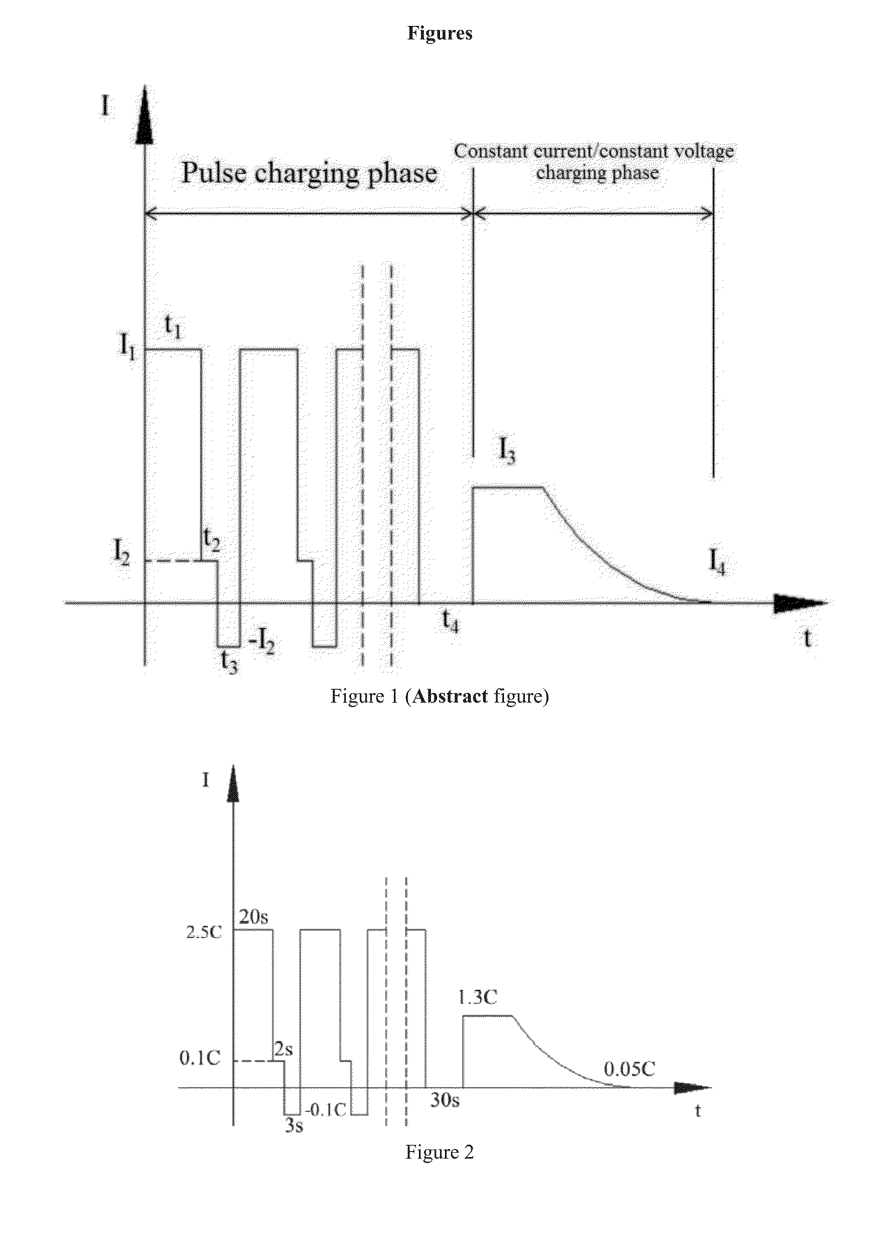
[0030]At 25° C., the battery was charged with the fast charging method of the present invention, according to the steps as follows:
1) the battery was charged with constant current of 3 C, and the charging time was 20 s;
2) the battery was charged with constant current of 0.05 C, and the charging time was 2 s;
3) the battery was discharged with constant current of 0.05 C, and the discharging time was 3 s, recycling until the voltage reached the pre-charging voltage of battery of 4.34V;
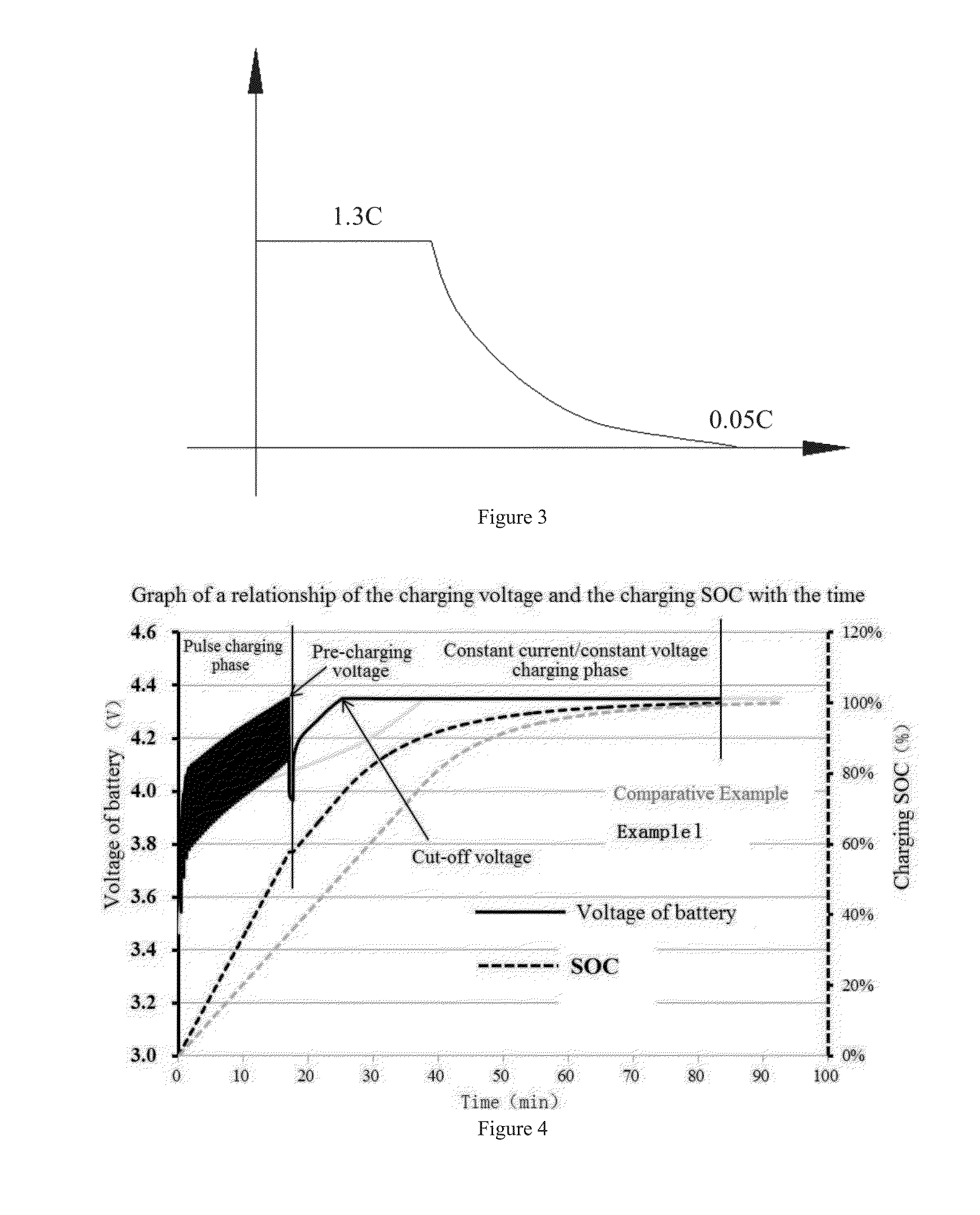
4) the battery was standed after the voltage reaching the pre-charging voltage of battery of 4.34V, and the rest time was 30 s, and then the battery was charged with constant current of 1.3 C until the voltage reaching a cut-off voltage of battery of 4.35V, and then the battery was charged with constant voltage until the current reaching the cut-off current of 0.05 C.
example 3
[0031]The battery was the same as Example 1.
[0032]At 25° C., the battery was charged with the fast charging method of the present invention, according to the steps as follows:
1) the battery was charged with constant current of 2.5 C, and the charging time was 30 s;
2) the battery was charged with constant current of 0.1 C, and the charging time was 5 s;
3) the battery was discharged with constant current of 0.1 C, and the discharging time was 10 s, recycling until the voltage reached the pre-charging voltage of battery of 4.34V;
4) the battery was standed after the voltage reaching the pre-charging voltage of battery of 4.34V, and the rest time was 10 s, and then the battery was charged with constant current of 1.3 C until the voltage reaching a cut-off voltage of battery of 4.35V, and then the battery was charged with constant voltage until the current reaching the cut-off current of 0.05 C.
PUM
 Abstract
Description
Claims
Application Information