
Fuel cell system, fuel cell vehicle, and method for evaluating operational failure of on-off valve

a fuel cell system and on-off valve technology, applied in battery/fuel cell control arrangement, process and machine control, instruments, etc., can solve the problem of deteriorating judgment reliability, affecting the reliability of evaluation, and difficult to detect an opening failure of the on-off valve, so as to prevent deterioration of judgment reliability and reduce the effect of reliability in evaluation

Active Publication Date: 2016-04-28
TOYOTA JIDOSHA KK
View PDF6 Cites 11 Cited by
  • Summary
  • Abstract
  • Description
  • Claims
  • Application Information

AI Technical Summary

Benefits of technology

The present invention relates to a fuel cell system and a vehicle with a fuel cell. The invention provides a method for evaluating the operation of an on-off valve in the fuel gas flow path from fuel gas tanks. The method uses a valve operation evaluation unit that calculates the total gas consumption of the fuel gas tank with an on-off valve and compares it to the standard gas pressure to determine if there is an opening failure of the valve. This evaluation process ensures that any opening failure of the valve can be detected with high reliability and prevents deterioration of judgment reliability. The invention also provides a method for detecting the opening failure of the valve by comparing the second total gas consumption with the first total gas consumption. This method ensures that the judgment is made based on the standard gas pressure when the fuel gas tank has been filled up to the standard pressure. The invention also provides a method for evaluating the operation of the valve after the fuel gas tank has been filled up to the standard pressure to prevent inadvertent judgment of no valve opening failure despite the fact that there is an opening failure of the valve. The invention also provides a fuel cell system and a vehicle with a fuel cell that can detect the opening failure of the valve with high reliability and prevent deterioration of judgment reliability.

Problems solved by technology

Since the evaluation method proposed in the patent literature referred to above assumes a single fuel tank, a similar evaluation method could not be applied to a configuration of multiple fuel gas tanks.
This is because, if an operation is carried out where the fuel gas is supplied from multiple fuel gas tanks at the same time, the following problem is likely to occur: Assuming that all the outlet sides of the on-off valves in the multiple fuel gas tanks are converged co connect to the pressure control valve via a fuel supply pipe provided with a pressure sensor, it is hard to detect an opening failure of the on-off valve from sense cause at the tank mouthpiece of the fuel gas tank.
Then, the failure of the on-off valve, whether it be an opening failure or a shutting failure, cannot be judged simply by the supplied gas pressure on the tank side upstream from the pressure control valve in the fuel supply pipe, which lowers the reliability of the evaluation of a valve opening failure.
Even if the first and second total gas consumptions do not match, the difference would be limited to the range of detection error allowed for the supply gas pressure sensor or the range of leak allowed in the gas supply path.
However, as the gas supply proceeds, the amount of gas supplied from the fuel gas tank with an on-off valve with no opening failure is increased by the amount of stopped or decreased gas supply from the fuel gas tank having a faulty on-off valve, and the amount of gas remaining in the fuel tank having an on-off valve with no opening failure and the gas pressure therein rapidly drop down as compared to the case of no faulty valve.
On the contrary, since the degree of decrease in the gas supply pressure in sight of the gas tank gets larger once the amount of fuel gas consumption reaches the predetermined gas consumption amount, it is more likely to happen that, if there is any opening failure of the on-off valve, the gas consumption differential between the first and second total gas consumptions grows too large to be limited within the predetermined threshold.

Method used


Image

  • Fuel cell system, fuel cell vehicle, and method for evaluating operational failure of on-off valve
  • Fuel cell system, fuel cell vehicle, and method for evaluating operational failure of on-off valve
  • Fuel cell system, fuel cell vehicle, and method for evaluating operational failure of on-off valve

Examples


Embodiment Construction

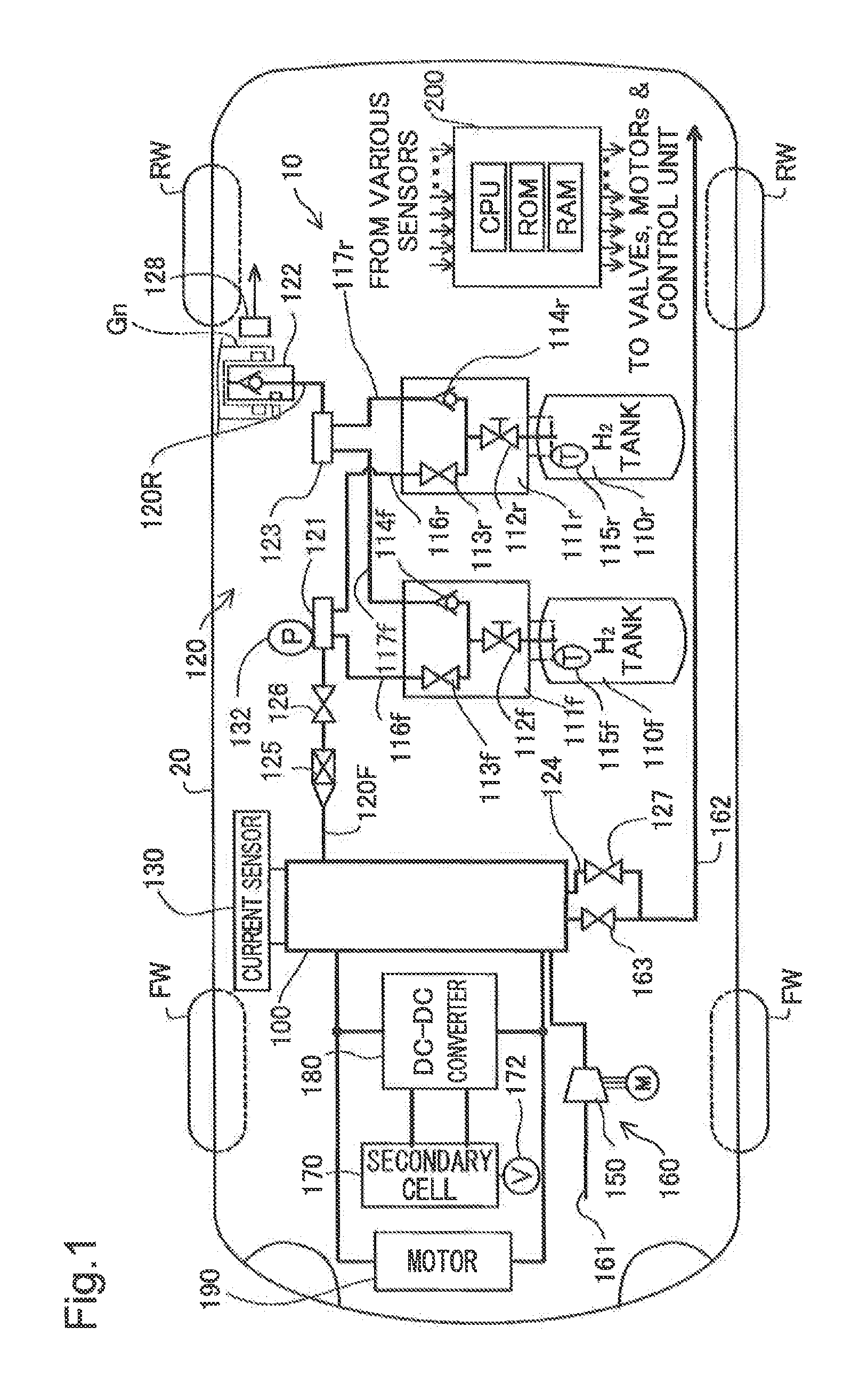
[0025]Embodiments of the present invention are described below in reference to the drawings. FIG. 1 is an illustrative drawing schematically showing a fuel cell system 10 as a first embodiment of the present invention.

[0026]As shown in the drawing, the fuel cell system 10 is mounted on a fuel cell vehicle 20 and comprises a fuel cell 100, a hydrogen gas supply system 120 including two gas tanks, an air supply system 160 including a motorized compressor 150, a cooling system, not shown, a secondary cell 170, a DC-DC converter 180, and a control unit 200. The fuel cell 100 is configured by layering multiple power generation modules equipped with a membrane electrode assembly (MEA), not shown, and is installed under the vehicle floor between the forward wheels FW and rear wheels RW. The fuel cell 100 generates power by electrically reacting hydrogen contained in the hydrogen gas supplied from the hydrogen gas supply system 120 described later and oxygen contained in the air supplied fr...


PUM


Abstract

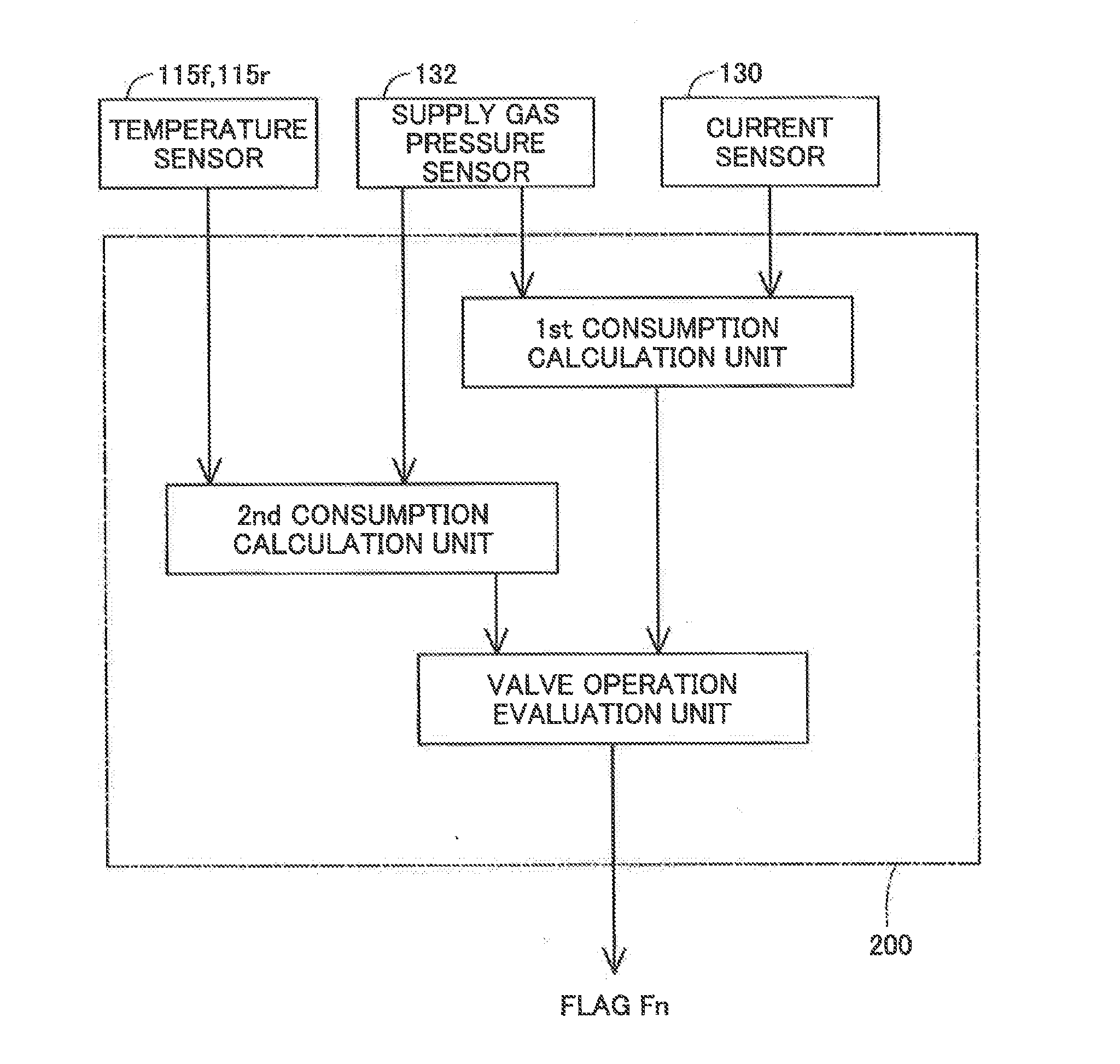
The control unit of the fuel cell system monitors the status of power generation of the fuel cell and calculates a total amount of the fuel gas consumption, based on the amount of power generated by the fuel cell, from a point in time when the supply gas pressure reaches a standard gas pressure. Another total amount of the fuel gas consumption is calculated based on a gas pressure change that corresponds to a decrease of the gas pressure from the standard gas pressure. Comparing two total amounts of the fuel gas consumptions, the evaluation is performed as whether the on-off valve in the fuel gas flow path from each of the fuel gas tanks to the fuel cell fails to be opened.

Description

CROSS-REFERENCE TO RELATED APPLICATION[0001]The present application claims priority from Japanese application P2014-217126 filed on Oct. 24, 2014, the content of which is hereby incorporated by reference into this application.BACKGROUND[0002]1. Field[0003]The present invention relates to a fuel cell system, a fuel cell vehicle, and a method for evaluating an operational failure of an on-off valve equipped in the fuel cell system.[0004]2. Related Art[0005]In supplying hydrogen gas stored in a fuel tank to a fuel cell, the fuel cell system reduces the gas pressure to a predetermined supply pressure using a pressure control valve. For such decompression adjustment, there has been known a mouthpiece of a fuel gas tank having a pressure control valve and a pressure sensor built therein in addition to an on-off valve. Assuming such a structure, it is proposed to use the gas pressure detected by the pressure sensor at the tank mouthpiece for evaluating an operational failure of the pressur...

Claims


Application Information

Patent Timeline
Patent Type & Authority Applications(United States)
IPC IPC(8): B60W20/00B60L11/18
CPCB60W20/50B60L11/1881B60W2710/28B60W2510/28B60L11/1809H01M8/04686H01M8/04992B60L3/0053B60L58/40B60L58/33B60L58/30Y02T10/70Y02E60/50Y02T90/40
Inventor SAITO, HIROMU
Owner TOYOTA JIDOSHA KK
Learn More