Exhaust system and methods for efficient exhaust heat recovery

a technology of exhaust heat recovery and exhaust system, which is applied in the direction of mechanical equipment, machines/engines, electric control, etc., can solve the problems of limited exhaust heat recovery amount available from the system, large heat recovery portion of exhaust gas flow, and difficulty in packaging separate heat exchangers in vehicles, etc., to achieve efficient and expeditious heat recovery, increase heat recovery, and reduce size, weight and cost

Active Publication Date: 2016-04-28
FORD GLOBAL TECH LLC
View PDF10 Cites 19 Cited by
  • Summary
  • Abstract
  • Description
  • Claims
  • Application Information

AI Technical Summary

Benefits of technology

[0003]The inventors have recognized issues with such approaches and herein describe a system and methods for heating engine coolant by transferring heat from an exhaust flow to the engine coolant via a heat exchanger positioned in an exhaust gas heat recovery line coupled to the EGR cooler responsive to an EGR valve position. In particular, an exemplary EGR cooler combined with an exhaust heat recovery device is presented that allows exhaust gas to transfer heat to engine coolant via a branching pathway of the EGR cooler. That is, an exhaust system configured according to the present disclosure allows exhaust gas to be routed to both an EGR and/or the exhaust gas heat exchanger based on EGR valve actuation. The system further allows for differential actuation of exhaust flows to distribute the exhaust gasses to both the EGR and exhaust heat exchanger, which enables a differential control of the exhaust flows therein and t

Problems solved by technology

However, a cooled EGR has the disadvantage that exhaust heat recovery can only occur when exhaust gas is flowing in the EGR, which limits the amount of exhaust heat recovery available from the system.
Another disadvantage is that exhaust heat recovery is only a portion of the exhaust gas flow, which may be as low as 25% or lower in some instances relative to the total exhaust flow.
However, while the exhaust heat recovered may be increased compared to FIG. 1A (e.g., via a more full exhaust heat recovery and independence relative to the EGR flow), a separate heat exchanger may be large and difficult to package in a vehicle.
In addition, heat exchangers may be heavy and/or expensive, which increases the cost of the vehicle.
Moreover, packa

Method used


Image

  • Exhaust system and methods for efficient exhaust heat recovery
  • Exhaust system and methods for efficient exhaust heat recovery
  • Exhaust system and methods for efficient exhaust heat recovery

Examples


Embodiment Construction

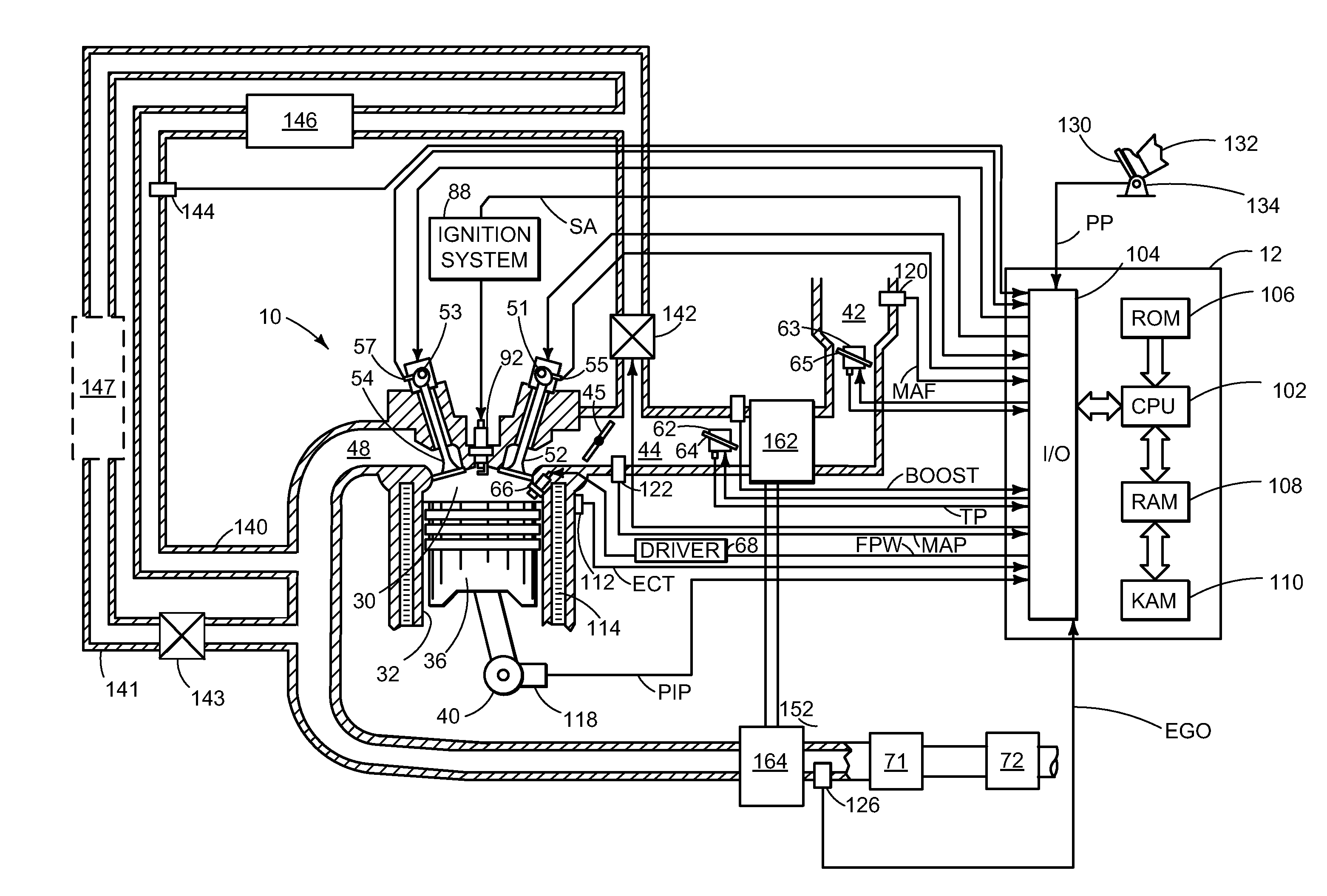
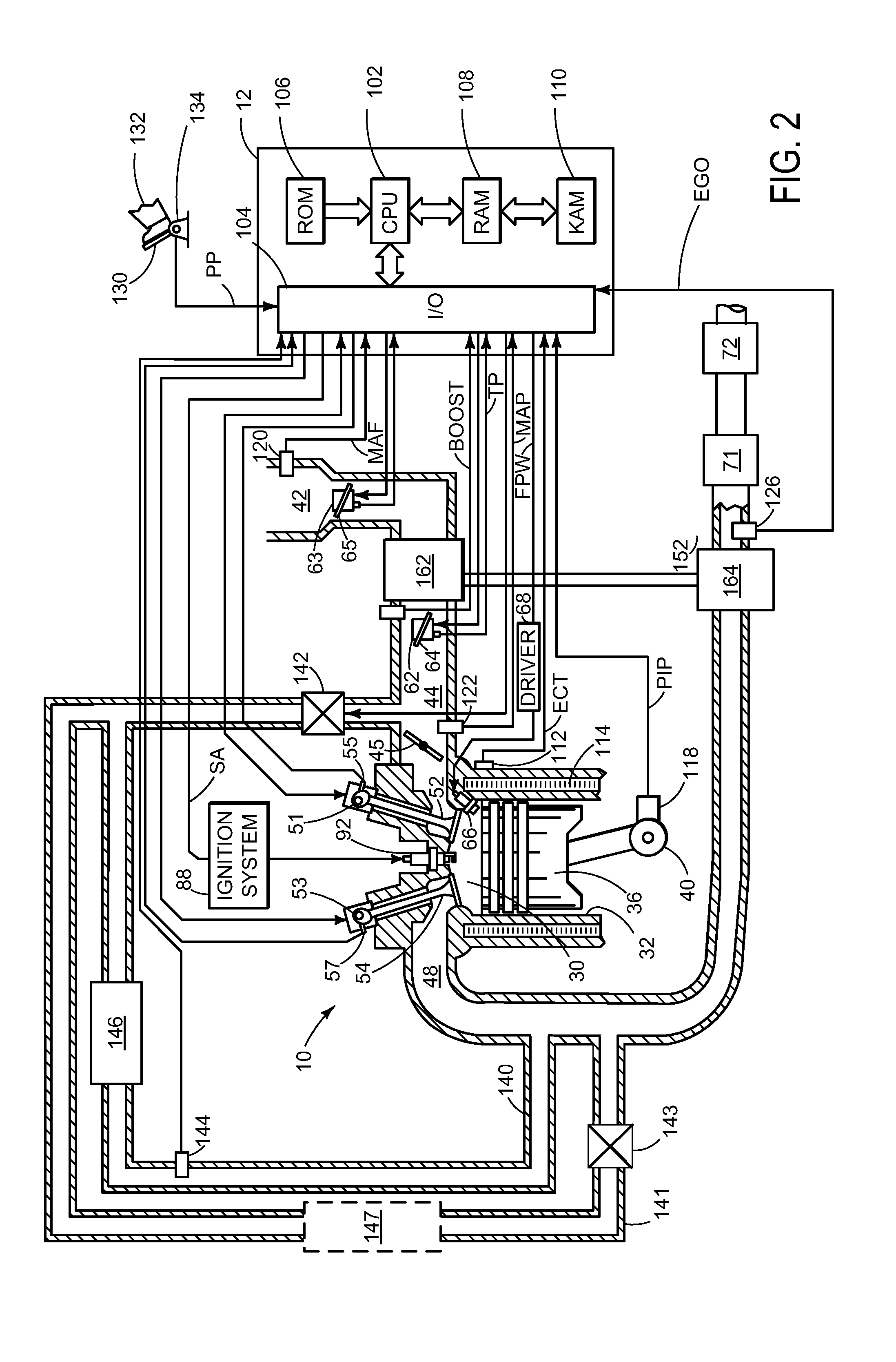
[0015]Upon starting a car in cold conditions, passengers may desire expedient cabin warming for a comfortable driving experience. Because cabin air is heated by engine coolant routed to the heater core, heat generated by an engine may be the primary source of heat for the passenger compartment in some instances. Thus, to reach a threshold cabin temperature above which it is possible to turn off the engine during vehicle operation, for example, to reduce fuel consumption in a hybrid vehicle, the engine may be operated until sufficient heat has been transferred to the engine coolant. For this reason, FIG. 2 shows an example hybrid vehicle system. Then, FIGS. 3-6 illustrate exemplary exhaust systems with an EGR cooler coupled to an exhaust gas heat recovery line configured and operated according to the present disclosure. FIGS. 7 and 8 further show example methods for changing the operating mode of the vehicle by adjusting an exhaust flow pathway based on valve states whereas FIG. 9 il...


PUM


Abstract

Systems and methods are described for heating engine coolant by transferring heat from an exhaust flow to the engine coolant via a heat exchanger positioned in an exhaust gas heat recovery line coupled to the EGR cooler responsive to an EGR valve position. In one particular example, a branching pathway of the EGR cooler is positioned downstream of the EGR cooler and allows exhaust gas to be routed to the EGR cooler and/or exhaust gas heat exchanger based on the EGR valve position, which allows for control of the amount of heat transferred to the engine coolant as well as exhaust gas recirculation into the engine. With this arrangement, a cabin temperature of a hybrid vehicle may be increased as quickly as possible under cold start conditions to allow the engine to be quickly turned off after heating the vehicle cabin.

Description

FIELD[0001]The present description relates to an exhaust system and methods for efficiently recovering exhaust heat during vehicle operation.BACKGROUND AND SUMMARY[0002]Engine systems use several methods to warm up engine coolant during operation. For example, FIGS. 1A-C illustrate example schematic exhaust systems previously implemented. In one example shown in FIG. 1A, the exhaust system includes a cooled EGR arrangement that is used to transfer exhaust heat to the engine coolant. However, a cooled EGR has the disadvantage that exhaust heat recovery can only occur when exhaust gas is flowing in the EGR, which limits the amount of exhaust heat recovery available from the system. Another disadvantage is that exhaust heat recovery is only a portion of the exhaust gas flow, which may be as low as 25% or lower in some instances relative to the total exhaust flow. Other examples are shown in FIGS. 1B and 1C that include using a separate exhaust heat recovery heat exchanger and valve ass...

Claims


Application Information

Patent Timeline
IPC IPC(8): F02M25/07
CPCF02M25/0771F02M25/0726F01N5/02F01N2240/36F01N2410/06F01P2037/02F02M26/28F02M26/35F02M2026/001Y02T10/12F01N3/02F02D41/0052F02D41/068
Inventor BRAMSON, ERIC DAVID
Owner FORD GLOBAL TECH LLC
Why Eureka
Try Eureka