Sealing element and wound-type solid state electrolytic capacitor thereof

Active Publication Date: 2016-04-28
APAQ TECH
View PDF10 Cites 5 Cited by
  • Summary
  • Abstract
  • Description
  • Claims
  • Application Information

AI Technical Summary

Benefits of technology

[0016]The present disclosure has at least the following improvements: The present disclosure provides the exterior convex portion of the sealing element can absorb the stress by the deformation of the sealing element, such that the sealing element, the outer surface of the circuit board, and the capacitor terminals mutually maintain a certain distance from each other, while room is provided to allow air flow for gases generated during soldering and welding in order to improve soldering quality.
[0017]Furthermore, the present disclosure provides a gap between the sealing element and the capacitor element by having the interio

Problems solved by technology

When the capacitor element 2 undergoes thermal deformation, if the element is compressed onto the inside surface of the sealing element 3, the capacitor element will undergo stress due to deformation that may damage the insulation layer or dielectric layer of the capacitor element 2, and may result in current leakage.
On the other hand, the hermetic seal between sealing element 3 and capacitor casing 1 maybe be destroyed due to compression by the capacitor element 2, such that moisture or other impurities may enter the capacitor casing, which can damage the insulation of the capacitor element 2.
As such, problems might surface such as (1) during soldering the capacitor, internal pressure of the capacitor case might increase as the temperature rises within, the sealing member 3 might be pressed o

Method used


Image

  • Sealing element and wound-type solid state electrolytic capacitor thereof
  • Sealing element and wound-type solid state electrolytic capacitor thereof
  • Sealing element and wound-type solid state electrolytic capacitor thereof

Examples


Example

First Embodiment

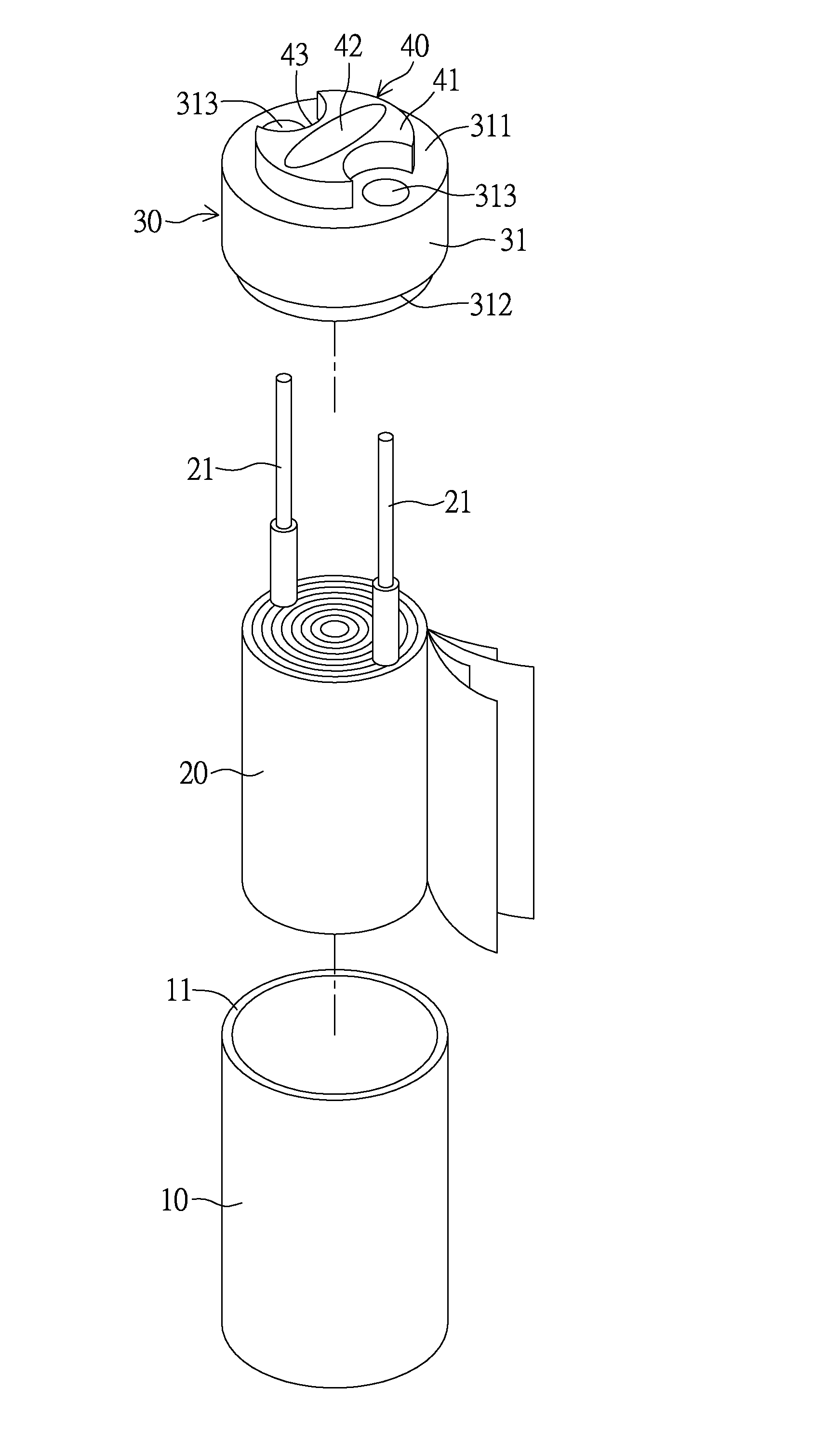
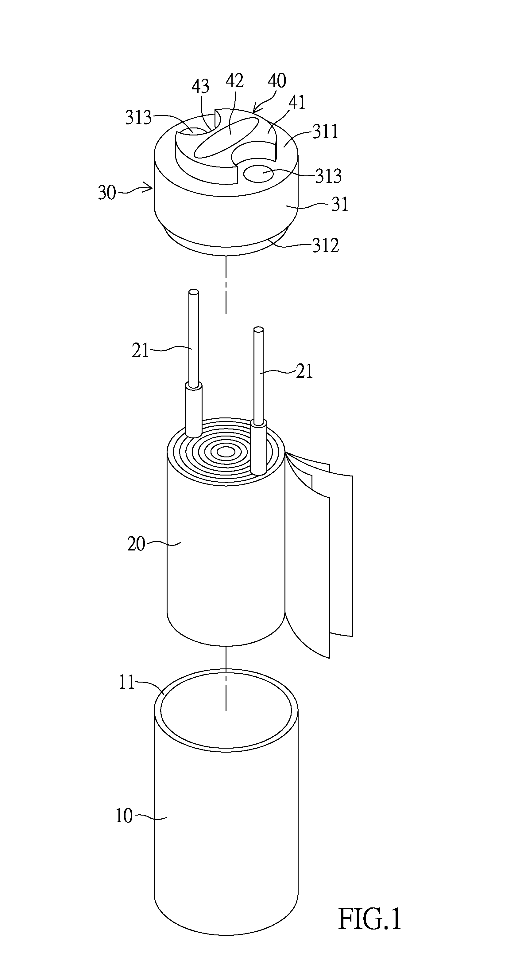
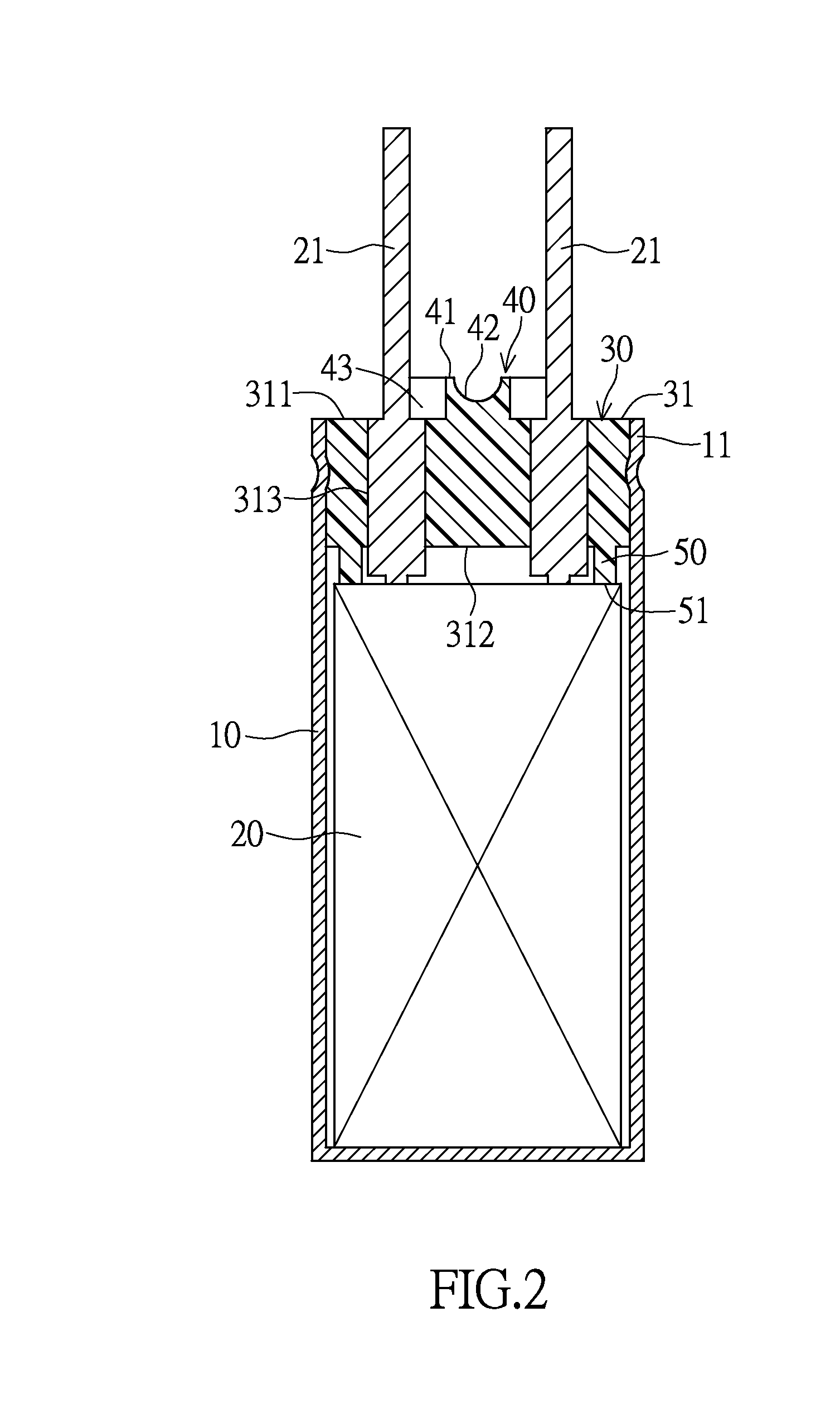
[0032]Please refer to FIGS. 1 and 2 as a structural illustration of a wound-type solid state electrolytic capacitor of a sealing element in accordance with the instant embodiment. The sealing element includes a capacitor casing 10, a capacitor element 20, and a sealing element 30. The capacitor casing 10 is a casing having a sealed end and an open end 11. The capacitor element 20 is arranged in the capacitor casing 10, the capacitor element 20 is formed by wounding anode foil and cathode foil together, and the capacitor element further has two terminals 21. The sealing element 30 is arranged at the open end 11 of the capacitor casing 10, and provides excellent hermetic sealing with the capacitor casing 10 in order to group the capacitor element 20 in the capacitor element 10, prevent moisture from entering the interior of the capacitor casing 10, and maintain insulation between the anode foil and the cathode foil of the capacitor element 20.

[0033]As shown in FIGS. 3 ...

Example

Second Embodiment

[0040]As shown in FIG. 8 as the second embodiment of the instant disclosure, the sealing member 30 has a plurality of exterior convex portion 40 arranged on the first surface 311 of the cover body 31. In the instant embodiment, the exterior convex portion 40 is defined as the plurality of protrusions protruding from the first surface 311 of the cover body 31. The protrusions extend from the first surface 311 and towards a direction away from the first surface 311. Each protrusion has the first abutting surface 41 arranged on the apex thereof. As shown in FIG. 8, each protrusion of the exterior convex portion 40 is spaced apart from another protrusion by a gap 44 so that none of the protrusions are connected to one another.

[0041]Each exterior convex portion 40 of the instant embodiment is separated by a gap 44 from another exterior convex portion 40, and each gap 44 that is arranged between two adjacent exterior convex portions 40 is a recessed space, so that any two...

Example

Third Embodiment

[0042]FIG. 9 illustrates the third embodiment of the instant disclosure. The third embodiment is a modification of the sealing element 30 as disclosed in the first embodiment. The cover body 31 of the instant disclosure has two annularly shaped ribs arranged on the second surface. The two annular ribs make up the two interior convex portions 50, and the two interior convex portions 50 extend from the second surface 312 and towards a direction away from the second surface 312. Each interior convex portion 50 has a second abutting surface 51 arranged on an apex thereof, and the second abutting surface 51 is partially in contact with the outer surface of the capacitor element 20.

[0043]Notably in the embodiment, the quantity of interior convex portions 50 that are arranged on the second surface of the cover body 31 of the sealing member 30 is not limited to one, and can be increased as required.


PUM


Abstract

A sealing element of the instant disclosure includes a cover body, an exterior convex portion, and an interior convex portion. The cover body has a first surface, a second surface arranged opposite to the first surface, and a pair of terminal holes formed on the cover body and extending through the first and second surfaces. The exterior convex portion has at least one first abutting surface arranged on the first surface of the cover body and an expansion space formed concavely in the exterior convex portion. The interior convex portion has at least one second abutting surface arranged on the second surface of the cover body. Specifically, the sealing element is configured to prevent the capacitor element from swaying, so that the electrical property of the wound-type solid state electrolytic capacitor with the sealing element can be improved.

Description

BACKGROUND OF THE INVENTION[0001]1. Field of the Invention[0002]The instant disclosure relates to a sealing element and wound-type solid state electrolytic capacitor thereof; in particular, to a sealing element and wound-type solid state electrolytic capacitor therefor for acoustics[0003]2. Description of Related Art[0004]For acoustics components, capacitors are widely used for filtering, decoupling, high-frequency compensation, and providing direct feedback. Depending on the structure and manufacturing process, capacitors can be divided into a variety of classes. Specifically in audio systems, since characteristics such as large frequency response and current are required, thus, aluminum electrolytic capacitors are most widely used.[0005]As shown in FIG. 12, the conventional wound-type solid state electrolyte capacitor comprises a capacitor casing 1, a capacitor element 2, and the sealing member 3. One end of the capacitor casing has an open end, the sealing element 3 is disposed i...

Claims


Application Information

Patent Timeline
IPC IPC(8): H01G9/10H01G9/15
CPCH01G9/151H01G9/10
Inventor LIN, CHING-FENGCHEN, MING-TSUNG
Owner APAQ TECH
Why Eureka
Try Eureka