
Method of producing a halogen lamp and halogen lamp

a technology of halogen lamps and halogen lamps, which is applied in the manufacture of electric discharge lamps, electric discharge tubes/lamps, electrical appliances, etc., can solve the problems of unwanted offset of rays, easy scratching or other damage of the coating or layer provided externally on the lamp bulb, and increase the reflection factor, increase the absorption factor, and increase the temperature of the glow filament

Inactive Publication Date: 2016-05-05
VOSLA
View PDF2 Cites 0 Cited by
  • Summary
  • Abstract
  • Description
  • Claims
  • Application Information

AI Technical Summary

Benefits of technology

The invention provides a glass tube blanket made of hard glass, which can be easily processed into a lamp bulb due to the lower temperatures required for forming. The coating applied during dip-coating comprises an infrared radiation reflecting coating which helps to increase the efficiency of the lamp by back-reflecting infrared radiation power emitted from the glow filament. This leads to an increase in luminous flux and saves energy. Additionally, the often unwanted warming-up of the environment for halogen incandescent lamps is reduced since less infrared radiation is emitted through the lamp bulb.

Problems solved by technology

With such a halogen incandescent lamp, rays emitted from the luminous element do not impinge on the IR radiation reflecting coating directly but have to pass the wall of the lamp bulb first whereby an unwanted offset of the rays occurs due to refraction, as well as absorption occurs due to attenuation.
Furthermore, such a coating or layer provided externally on the lamp bulb may easily become scratched or be otherwise damaged by external impact since the coating is not protected by the lamp bulb.

Method used


Image

  • Method of producing a halogen lamp and halogen lamp
  • Method of producing a halogen lamp and halogen lamp
  • Method of producing a halogen lamp and halogen lamp

Examples


Embodiment Construction

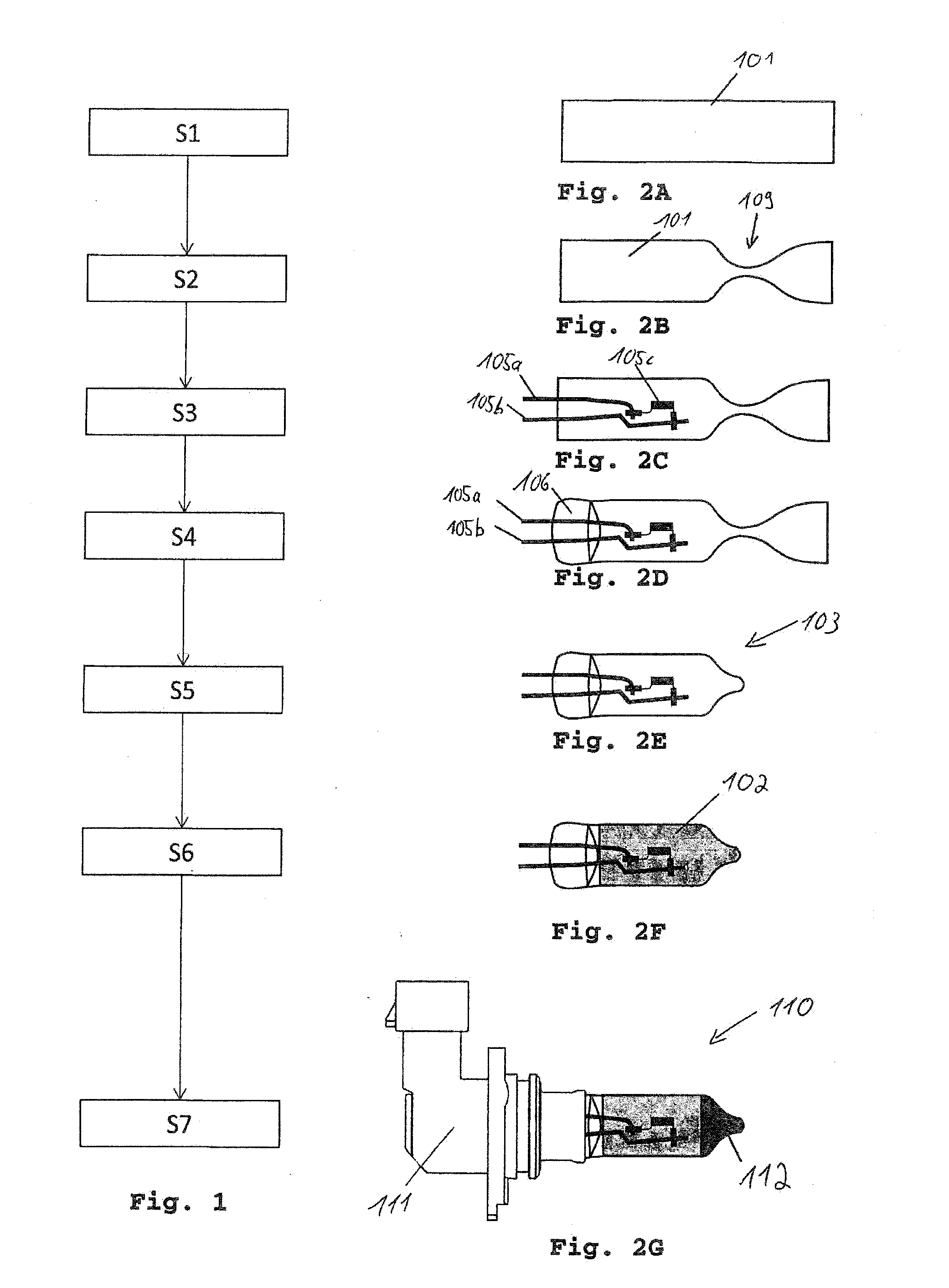
[0063]FIG. 1 in conjunction with FIGS. 2a to 2d shows a method for producing a halogen lamp which is known to the inventor. The method comprises steps S1 to S7. Herein the individual steps are explained with respect to FIGS. 2a to 2g which illustrate the respective state of the individual method steps during the production.

[0064]First step S1 refers to providing a glass tube blanket as is shown in FIG. 2a. The glass tube blanket 101 of FIG. 2a is made of for instance quartz glass or hard glass and is constructed as a circular hollow body illustrated in FIG. 2a in a side view. The length of the glass tube blanket 101 is already cut to the length required for producing a lamp bulb 103. Such an appropriate length is for example 8 cm. A glass tube blanket 101 which is thus cut to the correct length for producing a lamp bulb 103 is referred to as “sprengling” (i.e. a cut off piece).

[0065]Subsequent step S2 comprises the introduction of a pipette-like tapering 109 into the glass tube blan...


PUM


Abstract

The present invention relates to a method for producing a halogen lamp, comprising the following steps: providing a glass tube blanket; dip-coating of the glass tube blanket using a sol gel process having an inorganic coating; forming a lamp bulb from the coated glass tube blanket. The present invention relates further to a halogen lamp produced accordingly.

Description

TECHNICAL FIELD[0001]The present invention relates to methods for producing a halogen lamp. The invention relates further to a halogen lamp.BACKGROUND OF THE INVENTION[0002]A halogen incandescent lamp and a method for producing the same is described in DE 10 2005 019 113 A1. The halogen incandescent lamp comprises a lamp bulb having a luminous element contained therein. Furthermore, the lamp bulb is at least partly covered by an IR radiation reflecting coating by which heat radiation emitted from the luminous element in addition to the visible light shall be reflected back onto the luminous element. The application of the IR radiation reflecting coating is performed after deformation of the lamp bulb, in particular after main deformation of the lamp bulb. Thus, a conventional halogen incandescent lamp is produced in a first step and is being coated subsequently.[0003]With such a halogen incandescent lamp, rays emitted from the luminous element do not impinge on the IR radiation refl...

Claims


Application Information

Patent Timeline
IPC IPC(8): H01K1/32H01K5/00H01K3/00
CPCH01K1/325H01K5/00H01K3/005H01K1/32H01K7/02
Inventor WINKLER, MARKUSPOLSTER, MARTIN
Owner VOSLA
Learn More