
Sub-module, protection unit, converter, and control method thereof

Inactive Publication Date: 2016-05-05
NR ELECTRIC CO LTD +1
View PDF16 Cites 20 Cited by
  • Summary
  • Abstract
  • Description
  • Claims
  • Application Information

AI Technical Summary

Benefits of technology

The patent text describes a device that prevents a fault in a DC network from spreading to an AC network. The device also removes temporary faults without causing a sudden surge of current. The technical effects of this device include preventing damage to equipment and ensuring stable operation of the network.

Problems solved by technology

The disadvantages of the two modularized multilevel converters are that, when a fault occurs in a DC network, an alternating current (AC) network can provide a fault current to a fault point through a diode of the submodule, resulting in over-currents at AC and DC sides and at a converter valve, so the DC fault must be removed by tripping an line switch.
When a transient fault occurs in the DC network, AC line switches need to be tripped for all of the foregoing two modularized multilevel converters connected to the DC network, so that it takes a long time to restore electricity transmission.

Method used


Image

  • Sub-module, protection unit, converter, and control method thereof
  • Sub-module, protection unit, converter, and control method thereof
  • Sub-module, protection unit, converter, and control method thereof

Examples


Embodiment Construction

[0025]The technical solutions of the present invention are described in detail below in combination with accompanying drawings and specific embodiments.

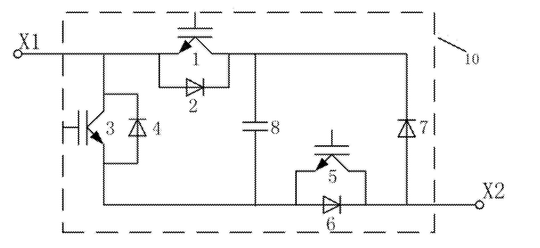
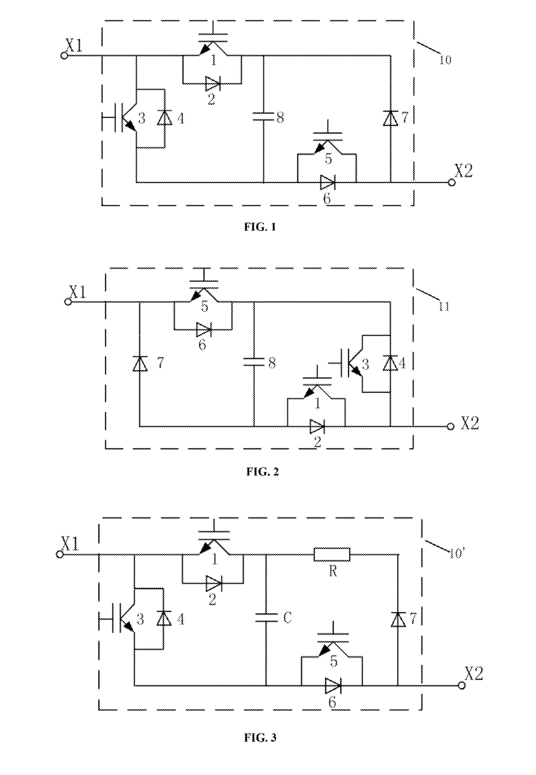
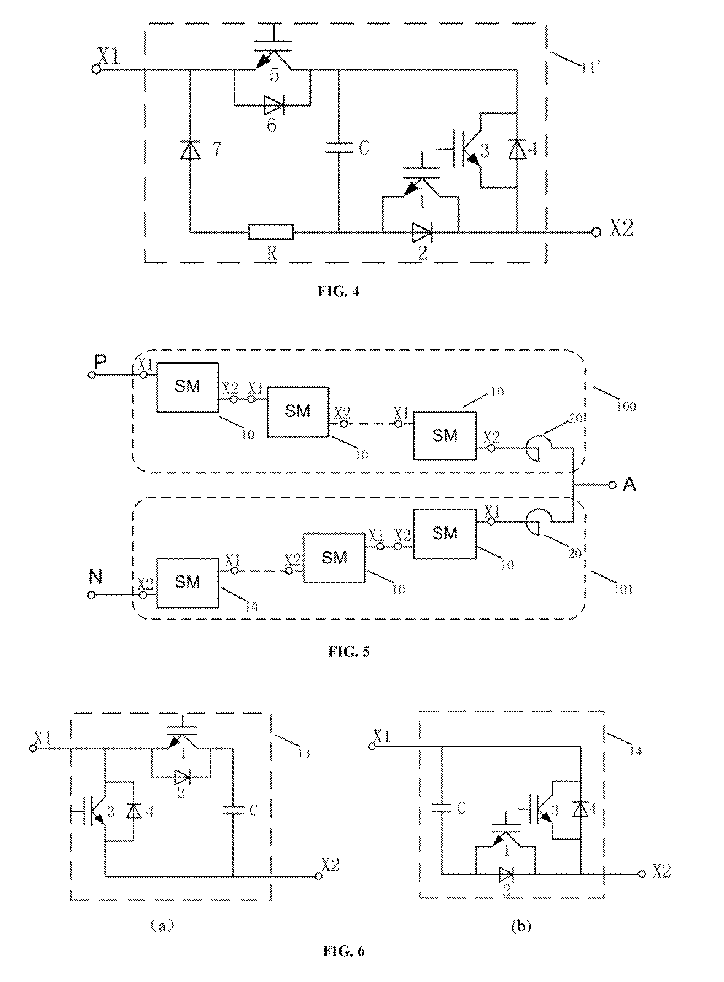
[0026]FIG. 1 to FIG. 4 are topological structure diagrams of preferred embodiments of a submodule provided by the present invention. FIG. 1 and FIG. 2 show a situation where no resistor is contained in the freewheeling diode branch. FIG. 3 and FIG. 4 show a situation where a resistor is contained in the freewheeling diode branch.

[0027]As shown in FIG. 1 and FIG. 2, the submodule comprises turn-off devices 1, 3, 5 in antiparallel connection with diodes and an energy storage element 8, where the turn-off device 1 is in antiparallel connection with the diode 2, the turn-off device 3 is in antiparallel connection with the diode 4, and the turn-off device 5 is in antiparallel connection with the diode 6. Each of the turn-off devices 1, 3, 5 may be a single controlled switch device (for example, a fully controlled device such as an IGBT, a...


PUM


Abstract

Disclosed are a submodule structure formed of an energy storage element, a first turn-off device, a second turn-off device, a third turn-off device, a freewheeling diode, a series resistor, and diodes respectively in antiparallel connection with the turn-off devices, and a converter completely or partially formed of the submodules. Also disclosed are a relevant protection unit and a control method for the converter. The converter can be locked when a direct current (DC) fault occurs to prevent an alternating current (AC) system from injecting a fault current into a DC network, so that a transient fault of the DC network can be removed without tripping an AC line switch, thereby rapidly restarting the system. A charging resistor is comprised in the submodule so that a charging resistor disposed at an AC side of the converter can be reduced and even may not be disposed.

Description

BACKGROUND OF THE INVENTION[0001]1. Field of the Invention[0002]The present invention relates to the field of power and electronics, and in particular, to a submodule, a protection unit, and a voltage source in multilevel convertor and a control method thereof.[0003]2. Description of Related Art[0004]A modularized multilevel converter is a new converter applicable to high voltage applications and attracting much attention in recent years. In the modularized multilevel converter, submodules are cascaded, where the state of each submodule is separately controlled to enable an alternating voltage outputted by the converter to approach a sine wave, thereby reducing a harmonic content in the output voltage. The modularized multilevel converter solves the series average-voltage problem existing in a two-level voltage source converter and has wide application prospects.[0005]In the “distributed energy stores and converter circuit” of Marquardt Rainer, a modularized multilevel converter (MM...

Claims


Application Information

Patent Timeline
IPC IPC(8): H02M1/32H02M7/483
CPCH02M1/32H02M7/4835H02M1/0095H02M7/483
Inventor DONG, YUNLONGCAO, DONGMINGTIAN, JIELI, HAIYINGWANG, NANNAN
Owner NR ELECTRIC CO LTD
Learn More