
Solar cell stack

a solar cell and stack technology, applied in the field of solar cell stacks, can solve problems such as insufficient efficiency

Active Publication Date: 2016-05-12
AZUR SPACE SOLAR POWER
View PDF9 Cites 7 Cited by
  • Summary
  • Abstract
  • Description
  • Claims
  • Application Information

AI Technical Summary

Benefits of technology

The solar cell stack described in this patent has high efficiency because it combines two solar cells with different lattice constants using a metamorphic buffer. This buffer reduces the number of dislocations, which helps to increase the overall efficiency of the solar cell stack compared to a stack of cells that match the lattice constant. This is achieved by selectively matching the bandgap energy of the solar cells using a high-quality metamorphic buffer.

Problems solved by technology

Only inadequate efficiencies are achieved, in particular by the InGaNAs subcell, due to the crystal quality.

Method used


Image

  • Solar cell stack
  • Solar cell stack
  • Solar cell stack

Examples


Embodiment Construction

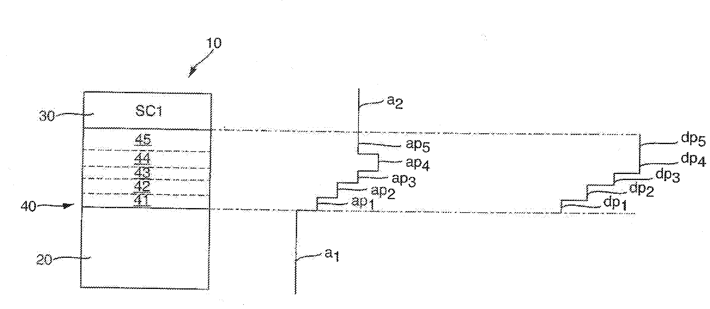
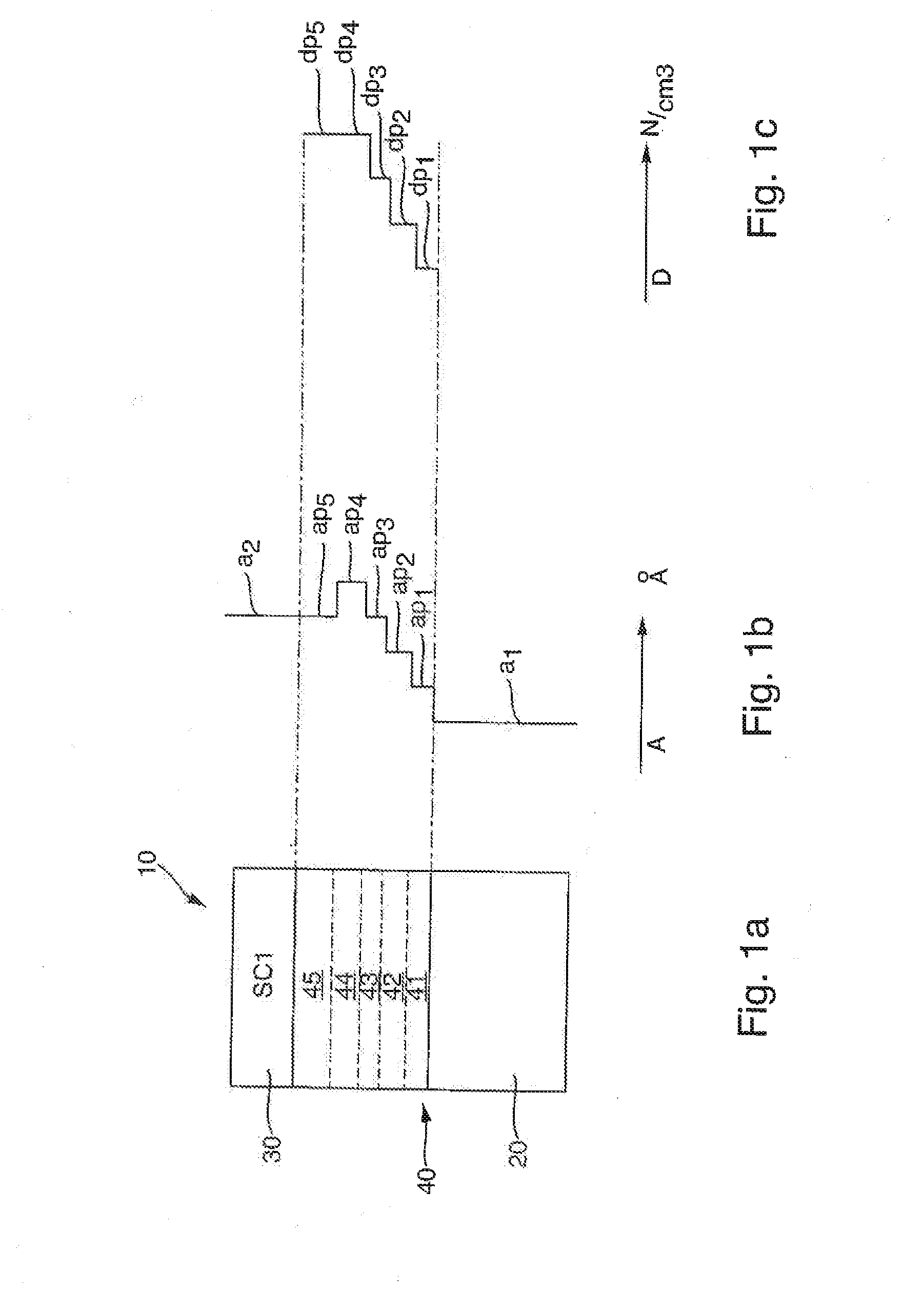
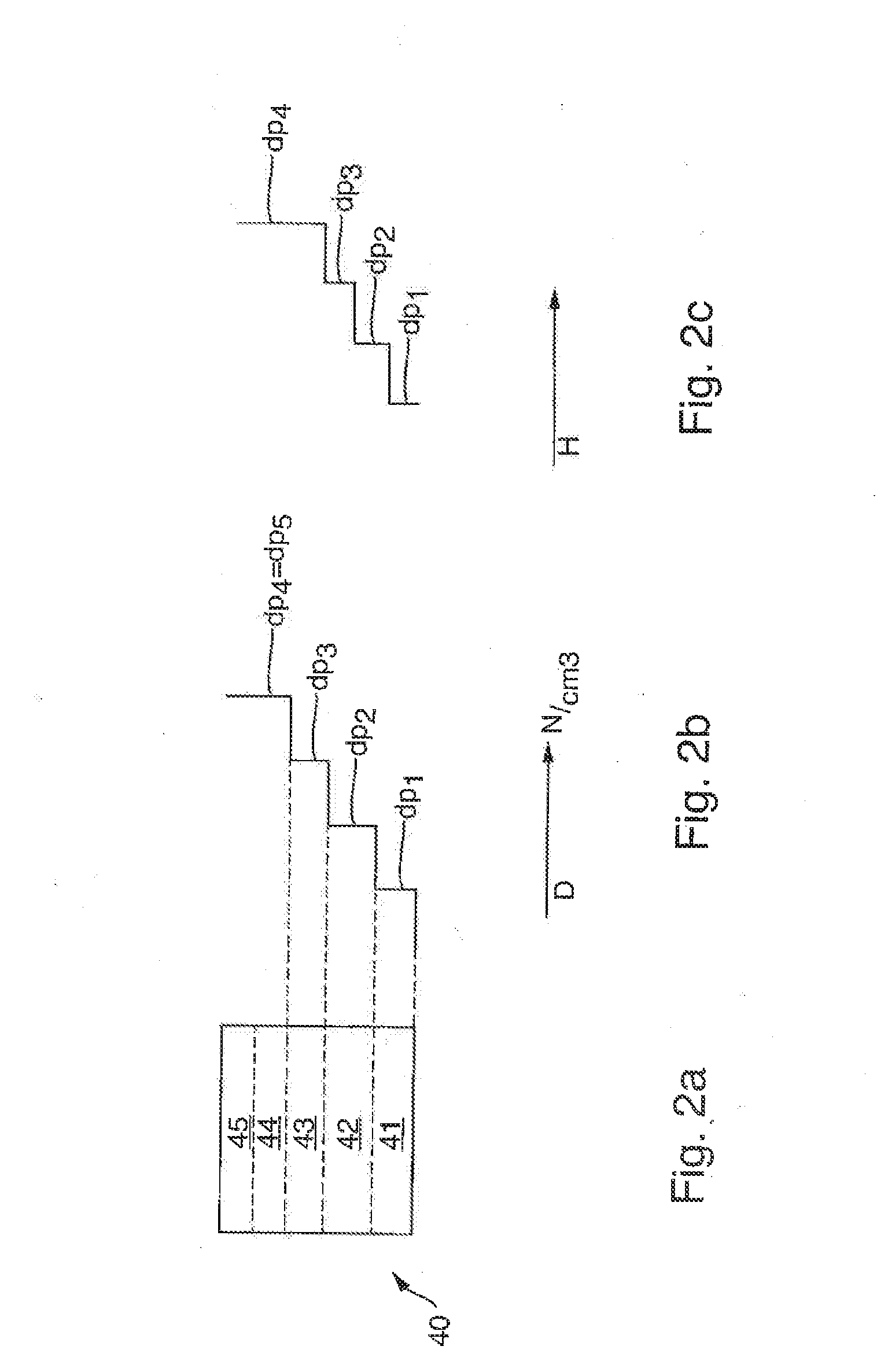
[0035]The illustration in FIG. 1 shows a solar cell stack 10, which comprises a first semiconductor solar cell 20 and a second semiconductor solar cell 30 and a metamorphic buffer 40 formed between semiconductor solar cell 20 and a second semiconductor solar cell 30.

[0036]First semiconductor solar cell 20 has a p-n junction made of a first material, which has a first lattice constant a1 and a first bandgap energy Eg1. Second semiconductor solar cell 30 has a p-n junction made of a second material, which has a second lattice constant a2 and a second bandgap energy Eg2. Second lattice constant a2 is bigger than first lattice constant al. The solar radiation enters through second semiconductor solar cell 30 and subsequently penetrates the buffer, after which it strikes first semiconductor solar cell 20. In one specific embodiment, which is not shown, the solar radiation enters through first semiconductor solar cell 20 and subsequently penetrates the buffer, after which it strikes secon...


PUM


Abstract

A solar cell stack, having a first semiconductor solar cell having a p-n junction made of a first material with a first lattice constant, and a second semiconductor solar cell having a p-n junction made of a second material with a second lattice constant, and the first lattice constant being at least 0.008 Å smaller than the second lattice constant, and a metamorphic buffer, the metamorphic buffer being formed between the first semiconductor solar cell and the second semiconductor solar cell, and the metamorphic buffer including a series of three layers, and the lattice constant increasing in a series in the direction of the semiconductor solar cell, and the lattice constants of the layers of the metamorphic buffer being bigger than the first lattice constant, two layers of the buffer having a doping, and the difference in the dopant concentration between the two layers being greater than 4E17 cm−3.

Description

[0001]This nonprovisional application claims priority under 35 U.S.C. §119(a) to European Patent Application No.14003768.0, which was filed in Germany on Nov. 10, 2014, and which is herein incorporated by reference.BACKGROUND OF THE INVENTION[0002]1. Field of the Invention[0003]The present invention relates to a solar cell stack.[0004]2. Description of the Background Art[0005]To achieve preferably high efficiencies for converting sunlight into electrical energy using solar cells, multijunction solar cells made of different semiconductor materials have been studied for a number of years now [W. Guter, Optimierung von III-V basierten Hochleistungssolarzellen (Optimizing III-V-based high-efficiency solar cells), Dissertation, University of Constance, Department of Physics, 2011]. Multijunction solar cells distribute the incident light to multiple solar subcells which are stacked on top of each other and have different bandgap energies. To achieve the highest efficiencies, the semicondu...

Claims


Application Information

Patent Timeline
Patent Type & Authority Applications(United States)
IPC IPC(8): H01L31/0687H01L31/0693H01L31/056
CPCH01L31/06875H01L31/0693H01L31/056H01L31/035272H01L31/0687H01L31/03042Y02E10/52Y02E10/544
Inventor FUHRMANN, DANIELGUTER, WOLFGANG
Owner AZUR SPACE SOLAR POWER
Learn More