
Composite Element and Use Thereof

a technology of composite elements and elements, applied in the field of composite elements, can solve the problems of not meeting the applicable fire protection requirements, no solutions have been demonstrated, and the weight per unit area of such interior furnishing elements must be observed, so as to prevent the spread or transmission of smoke, reduce weight, and reduce the effect of weigh

Inactive Publication Date: 2016-05-19
SCHOTT AG
View PDF7 Cites 24 Cited by
  • Summary
  • Abstract
  • Description
  • Claims
  • Application Information

AI Technical Summary

Benefits of technology

The invention is a lightweight composite panel with good optical properties and no streaks, low haze or low scattering behavior. The panel has a neutral rendition of colors and a high color rendering index. The ratio of the thickness of mineral glass or glass-ceramic panels to the thickness of all organic layers is advantageous for optical scattering behavior. This panel can be used as a smoke barrier element in fire protection to prevent the spread or transmission of smoke. The low weight and high fire protection of the panel make it a cost-effective solution with lower static load on construction.

Problems solved by technology

However, some applications, above all those in the field of transportation, such as in aircraft manufacture and electric vehicle manufacture, pose requirement profiles for which until now no solutions have been demonstrated in the prior art.
In addition to this, limits with respect to the weight per unit area of such interior furnishing elements have to be observed on account of requirements from the air travel industry, for example.
Although panels made of a polymer material do meet the requirements placed on the weight per unit area, they do not meet the applicable fire protection requirements.
However, an improvement in flame protection for such polymer panels always entails losses in terms of the transparency of such materials, as a result of which they then cannot be used for applications as viewing windows, for example.
Although known panels made of a glass / polymer laminate composite do meet the requirements placed on transparency and thermal safety, they do not meet those placed on weight per unit area, such as, for example, composite glass panels as are known, for example, as windshields for motor vehicles or as composite safety glass in the field of architecture.
Other glass / polymer laminate composite panels, such as those described below in the listing of the prior art, do not meet the applicable fire protection requirements.
Because panels according to the prior art do not meet the applicable specifications in aircraft manufacture, special permits of the respectively competent air travel authorities apply there.
In spite of this, however, such panels do not comply in any case with all of the requirements of international provisions in regard to fire safety protection, such as, for example, those that have been established by the FAA (Federal Aviation Administration) of the United States and imposed internationally, such as, for example, the JAR (“Joint Aviation Requirements”) or the CS (“Certification Specifications”) of the EASA.
Moreover, such panels do not have a scratch resistance that is comparable to that of glass, despite in part additional coatings with hard materials, such as those known in the prior art.
In order to counteract external effects, such as, for example, the danger due to impact of a stone, however, it is necessary in this case to observe a minimum thickness of the glass layers and, as a result of this, the weight savings are limited.
On account of the relatively thick organic layer, this composite panel does not afford any adequate fire protection safety, such as that necessitated, for example, in the requirements for air travel.
Here, too, a relatively thick plastic plate is proposed, which is likewise appreciably thicker than the glass layer, so that this composite panel does not meet the thermal safety requirements, such as those demanded in the requirements for air travel, for example.
A drawback is always that the plastic layer is too thick in relation to the glass thickness.
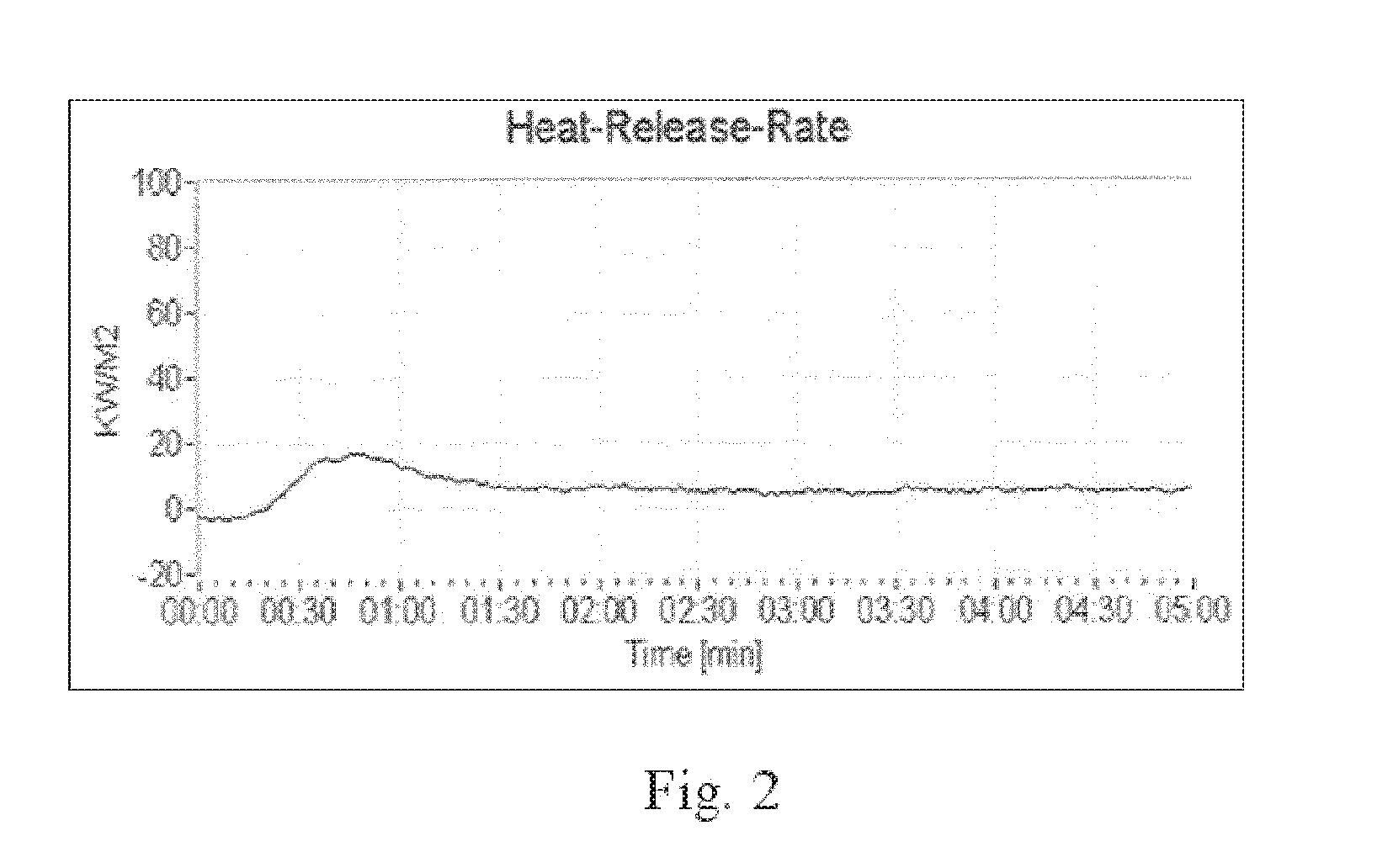
Such panels do not meet the thermal safety requirements of air travel, at least not the requirements with respect to the “heat release rate,” because the heat release is always too high, thereby supporting fire, nor do they meet the requirements according to the “vertical burner test,” because the proportion of organics in the composite panels is too high.
Because the thickness of the plastic support material is relatively greater in comparison to the thickness of the glass coating, this composite panel likewise does not meet the fire protection requirements, such as those stipulated in the requirements for air travel, for example.
Especially where the weight per unit area assumes a decisive role, attempts to adapt light materials to the thermal safety requirements have so far failed owing to the quality of the optical properties.
Any marked improvement in the thermal properties of polymeric materials in the direction of flame retardancy or in terms of flammability has always occurred at the expense of transparency in an unacceptable manner.
Usually, however, thermal prestressing processes are less suitable for thin glasses with a thickness of less than 1 mm or 0.5 mm.
However, in each case, the penetration depth needs to be tuned to the total thickness of the glass or glass-ceramic panel, since, if the tensile stress that is created in the interior of the glass or glass-ceramic panel during chemical hardening is too high, the glass or glass-ceramic panel will break.
A danger in the event of fires often ensues from the spread of smoke in buildings, entailing the danger of smoke poisoning for persons.

Method used


Image

  • Composite Element and Use Thereof
  • Composite Element and Use Thereof
  • Composite Element and Use Thereof

Examples


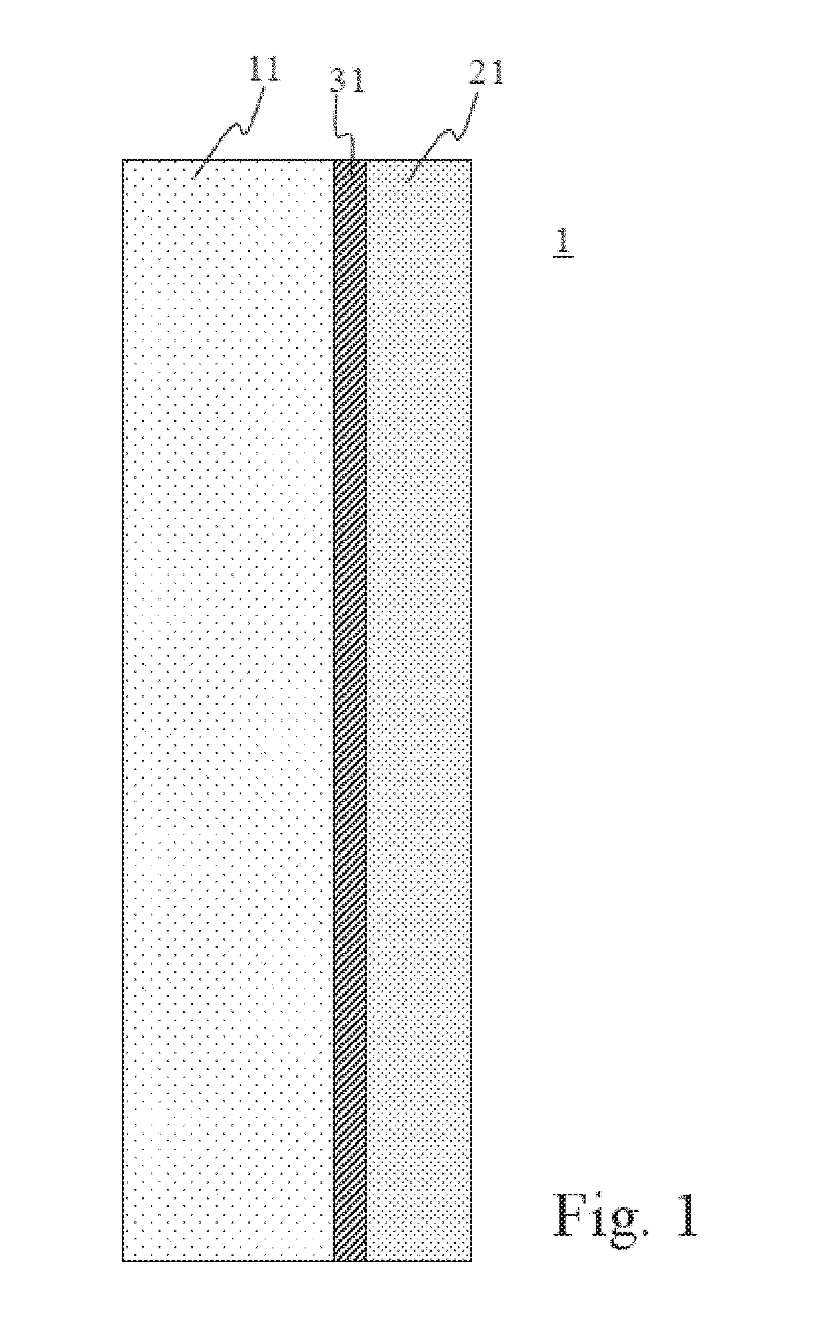
example 4

[0117]

MaterialThicknessGlass layerChemically prestressed aluminosilicate0.55mmglassOrganic layerOCA50μmASecond glassChemically prestressed aluminosilicate0.55mmlayerglass

[0118]Weight per unit area: 2.78 kg / m2.

[0119]Total thickness of the organic layers: 50 μm.

[0120]Ratio of the thickness of the glass panel to the total thickness of the organic layers: 1:0.045.

example 5

[0121]

MaterialThicknessGlass layerChemically prestressed aluminosilicate1.0mmglassOrganic layerInterlayer TPU350μmASecond glassChemically prestressed borosilicate0.7mmlayerglass

[0122]Weight per unit area: 4.61 kg / m2.

[0123]Total thickness of the organic layers: 350 μm.

[0124]Ratio of the thickness of the glass pane to the total thickness of the organic layers: 1:0.206.

example 6

[0125]

MaterialThicknessGlassChemically prestressed aluminosilicate glass0.55mmlayerOrganicInterlayer made of silicone-based, highly200μmlayer Atransparent plastic film, such as the one offeredby the company Wacker Chemie AG / D-Munichunder the trade name Tectosil ®SecondChemically non-prestressed borosilicate glass0.21mmglasslayer

[0126]Weight per unit area: 2.10 kg / m2.

[0127]Total thickness of the organic layers: 200 μm.

[0128]Ratio of the thickness of the glass pane to the total thickness of the organic layers: 1:0.263.


PUM

PropertyMeasurementUnit
total thicknessaaaaaaaaaa
transparencyaaaaaaaaaa

Abstract

A lightweight composite panel is provided that includes at least one mineral glass or glass-ceramic panel and at least one organic layer. The weight per unit area of the lightweight composite panel is in the range from 0.5 kg / m2 to 5.5 kg / m2, the ratio of the total thickness of the one or more mineral glass or glass-ceramic panels to the total thickness of all of the organic layers is from 1:0.01 to 1:1 and the total thickness of all of the organic layers is less than or equal to 350 μm. The lightweight composite panel complies with the thermal safety requirements of the air travel authorities and its “Total Heat Release,” measured in accordance with JAR / FAR / CS 25, App. F, Part IV & AITM 2.0006, is less than 65 kW×min / m2 and its flame time after removal of the flame in the “Vertical Bunsen Burner Test”, measured in accordance with FAR / JAR / CS 25, App. F, Part 1 & AITM 2.0002A, is less than 15 s.

Description

CROSS REFERENCE TO RELATED APPLICATIONS[0001]This application is a continuation of International Application No. PCT / EP2014 / 064887 filed Jul. 11, 2014, which claims benefit under 35 U.S.C. §119(a) of German Patent Application No. 10 2013 214 422.9 filed Jul. 24, 2013, the entire contents of both of which are incorporated herein by reference.BACKGROUND[0002]1. Field of the Invention[0003]The present invention relates to a composite element having at least one mineral glass or glass-ceramic layer and at least one organic layer that is adjacent to the glass or glass-ceramic layer and having a low total weight per unit area and a low heat release rate as well as to a method for the manufacture and use of such a composite element. The invention further comprises an interior aircraft window pane or lightweight window pane and a smoke barrier element with such a composite element.[0004]2. Description of Related Art[0005]Glass / plastic composite panels for use in vehicles on land, on water, ...

Claims


Application Information

Patent Timeline
Patent Type & Authority Applications(United States)
IPC IPC(8): B32B17/10B29C65/00B32B37/16B32B38/10B32B7/12B32B37/10
CPCB32B17/10798B32B17/10137B32B37/1018B32B37/10B32B37/16B32B38/10B29C66/45B29C66/7465B29C66/0224B32B2255/26B32B2307/412B32B2307/54B32B2307/542B32B2307/536B32B2307/3065B32B2419/00B32B2605/18B32B2309/02B32B2315/08B29L2031/778B32B2367/00B32B2383/00B32B2375/00B32B17/1077B32B7/12B32B17/10779B32B17/10036B32B17/10816B32B17/10018B32B17/10119B32B17/10862B32B17/10935B64C1/1484C03C3/083C03C3/091C03C21/002C03C27/10B32B17/10B32B17/10005
Inventor MEISS, JENSOTTERMANN, CLEMENSESEMANN, HAUKEFECHNER, JOERG HINRICHORTNER, ANDREASLIEBALD, RAINERKUREK, KLAUS-PETERHEISS-CHOUQUET, MARKUS
Owner SCHOTT AG
Learn More