Control device for internal combustion engine

a control device and internal combustion engine technology, applied in the direction of electric control, fuel injection apparatus, charge feed system, etc., can solve the problems of affecting exhaust emission performance and drivability, damage to the accuracy of air fuel ratio control of internal combustion engine, etc., to achieve the effect of reducing relative variation, reducing the amount of fuel supplied, and improving the accuracy of air fuel ratio control

Active Publication Date: 2016-05-19
HITACHI ASTEMO LTD
View PDF13 Cites 19 Cited by
  • Summary
  • Abstract
  • Description
  • Claims
  • Application Information

AI Technical Summary

Benefits of technology

[0010]According to the invention, it is possible to suppress a relative variation in an injection, amount of fuel supplied to each cylinder and, as a result, accuracy of an air fuel, ratio control of in internal combustion engine can be improved.

Problems solved by technology

However, regarding the injection amount of the fuel injection valve, it is known that a variation is caused in an injection flow rate of each fuel injection valve by a variation in manufacturing processes of the fuel injection valve at an initial stage and a secular degradation of the fuel injection valve after being mounted in the internal combustion engine.
Therefore, in a case where the variation in the injection amount of the fuel injection valve is large, an air fuel ratio control of the internal combustion engine is damaged in accuracy, and exhaust emission performance and drivability are affected.

Method used


Image

  • Control device for internal combustion engine
  • Control device for internal combustion engine
  • Control device for internal combustion engine

Examples


first embodiment

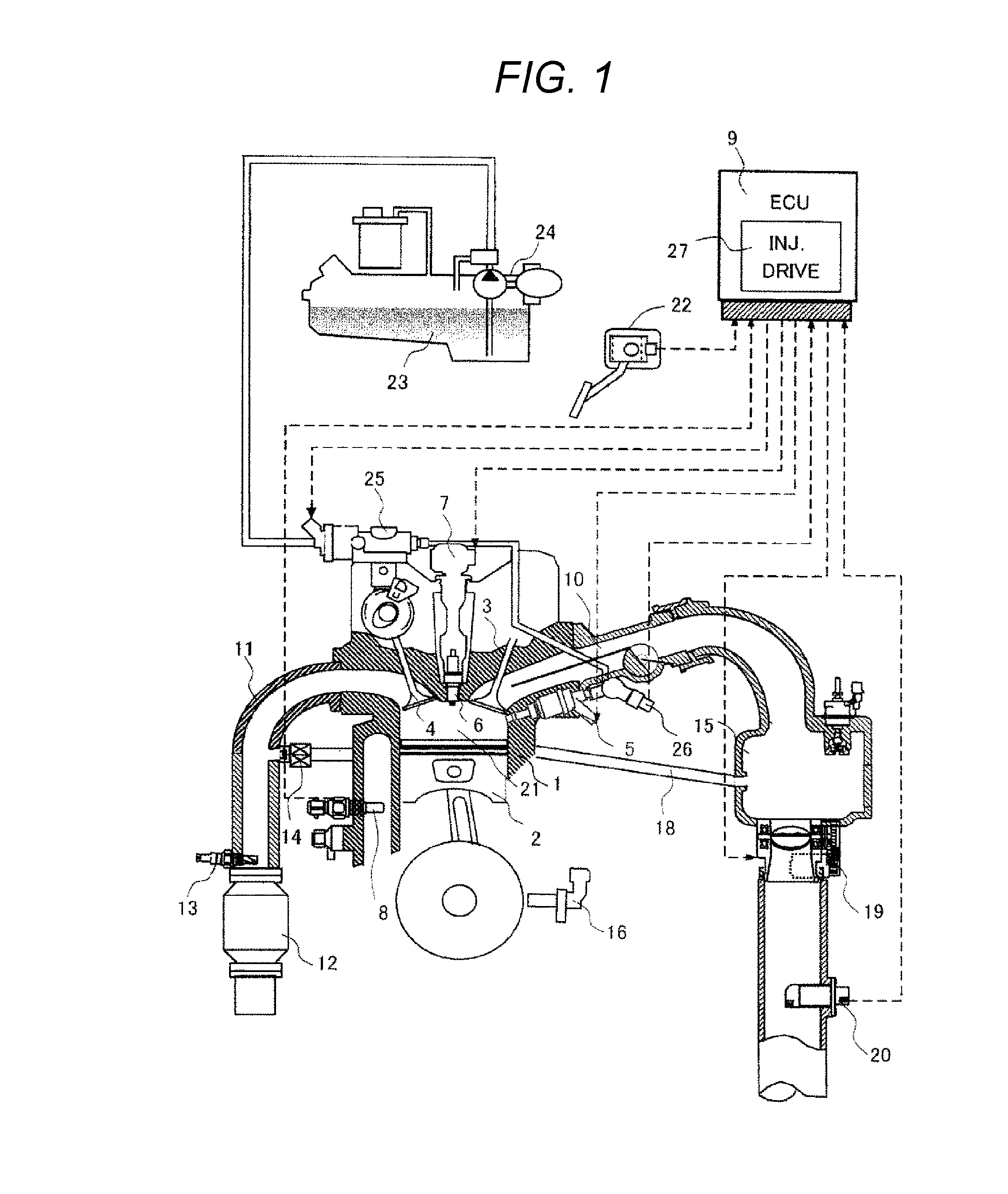
[0034]First, the description will be made about a configuration of an internal combustion engine system equipped with the fuel injection control device according to this embodiment. FIG. 1 is a diagram illustrating the entire configuration of the internal combustion engine system equipped with the fuel injection control device according to the embodiment.

[0035]As illustrated in FIG. 1, an engine (the internal combustion engine) is provided with a piston 2, an intake valve 3, and an exhaust valve 4. The air (intake air) flowing into the engine 1 passes through an air flow meter (AFM) 20 and is adjusted in its flow rate by a throttle valve 19, and is supplied to a combustion chamber 21 of the engine 1 from a collector 15 serving as a branch portion through an intake pipe 10 and the intake valve 3.

[0036]The fuel is supplied from a fuel tank 23 to a high pressure fuel pump 25 by a low pressure fuel pump 24, and is increased in pressure necessary for the fuel injection by the high pressu...

first example

[0069]FIG. 7 is a diagram for describing a correction method according to a first example, and FIG. 8 is a diagram illustrating the corrected drive pulse width in FIG. 7 and the drive current. In the first example, the fuel injection valve having a minimum value (Min in FIG. 6) of the difference between the valve-opening response delay time and the valve-closing response delay time of the fuel injection valve provided in the engine is selected, and the drive pulse width is corrected in accordance to the characteristic of the fuel injection, valve having the minimum value.

[0070]Specifically, first, as described above, the valve-opening response delay time and the valve-closing response delay time of the fuel injection valve 5 are calculated with respect to the fuel injection valves #n to #n+3 by the fuel injection valve-closing detection unit (the valve-closing response delay time calculation unit) 9d, the fuel injection valve-opening detection unit (the valve-opening response delay ...

second example

[0075]FIG. 9 is a diagram for describing a correction method according to a second example, and FIG. 10 is a diagram illustrating the corrected drive pulse width in FIG. 9 and the drive current. In the second example, the fuel injection valve having a maximum value (max in FIG. 6) of the difference between the valve-opening response delay time and the valve-closing response delay time of the fuel injection valve provided in the engine is selected, and the drive pulse width is corrected in accordance to the characteristic of the fuel injection valve having the maximum value.

[0076]Specifically, similarly to the first example, the valve-opening response delay time and the valve-closing response delay time of the fuel injection valve 5 are calculated with respect to the fuel injection, valves #n to #n+3. by the fuel injection valve-closing detection unit (the valve-closing response delay time calculation unit) 9d, the fuel injection valve-opening detection unit (the valve-opening respon...


PUM


Abstract

Provided is a control device for an internal combustion engine which can suppress a relative variation in the fuel injection amount for each cylinder. A drive pulse width to drive the fuel injection valve for injecting the fuel is calculated according to a driving state of the internal combustion engine, any one or both of a valve-opening response delay time and a valve-closing response delay time with respect to a drive pulse signal of the fuel injection valve for each fuel injection value are calculated, and the drive pulse width is corrected to make an injection amount of each fuel injection valve matched to a predetermined injection amount based on any one or both of the valve-opening response delay time and the valve-closing response delay time calculated for each fuel injection valve.

Description

TECHNICAL FIELD[0001]The present invent ion relates to a control device which controls a fuel injection valve of an internal combustion engine.BACKGROUND ART[0002]In an internal combustion engine, there is provided a control device which calculates an appropriate injection amount according to a driving state and controls a fuel injection valve to supply the fuel. A magnetic force generated by a current flowing to a coil built in the fuel injection valve for opening and maintaining an open state of the fuel injection valve is asserted to a valve body of the fuel injection valve, so that the valve body is opened or closed and the fuel is injected by the corresponding amount according to a valve-opening period.[0003]Herein, the amount (the injection amount) of the injected fuel is mainly determined by a differential pressure between a pressure of the fuel and an atmosphere pressure of an injection port of the fuel injection valve and a time period during which the open state of the val...

Claims


Application Information

Patent Timeline
Patent Type & Authority Applications(United States)
IPC IPC(8): F02D41/30F02D41/00F02M63/00F02D41/38
CPCF02D41/3005F02M63/0015F02D41/008F02D41/3809F02D41/20F02D41/0085F02D41/2467F02D2041/2055
Inventor TOYOHARA, MASAHIROMUKAIHARA, OSAMUSAKAMOTO, HIDEYUKIFUKUDA, TAKAOKAWATSU, MASAYOSHI
Owner HITACHI ASTEMO LTD
Why Eureka
Try Eureka