Welding device

a welding device and a welding technology, applied in the direction of electric variable regulation, instruments, manufacturing tools, etc., can solve the problems of degrading welding performance, unable to produce various welding output waveforms with steep changes, and the increased l value of dcl can not achieve the effect of high-quality welding

Active Publication Date: 2016-05-26
PANASONIC INTELLECTUAL PROPERTY MANAGEMENT CO LTD
View PDF4 Cites 4 Cited by
  • Summary
  • Abstract
  • Description
  • Claims
  • Application Information

AI Technical Summary

Benefits of technology

[0018]The welding device of the present disclosure, as described above, changes the inverter frequency so as to be suitable for the output-on period, offering high-quality welding.

Problems solved by technology

According to the conventional inverter control described above, a low inverter frequency increases the ripple factor of welding voltage, and causes arc interruption, thereby degrading welding performance.
However, an increased L value of DCL can fail to produce various welding output waveforms with steep changes.
However, increasing an inverter frequency also increases a switching loss of a switching element, thereby heating up switching section 102.
This has caused a necessity of countermeasures against heat.

Method used


Image

  • Welding device
  • Welding device
  • Welding device

Examples


exemplary embodiment 1

[0026]The structure of the exemplary embodiment is described with reference to FIG. 1 through FIG. 4.

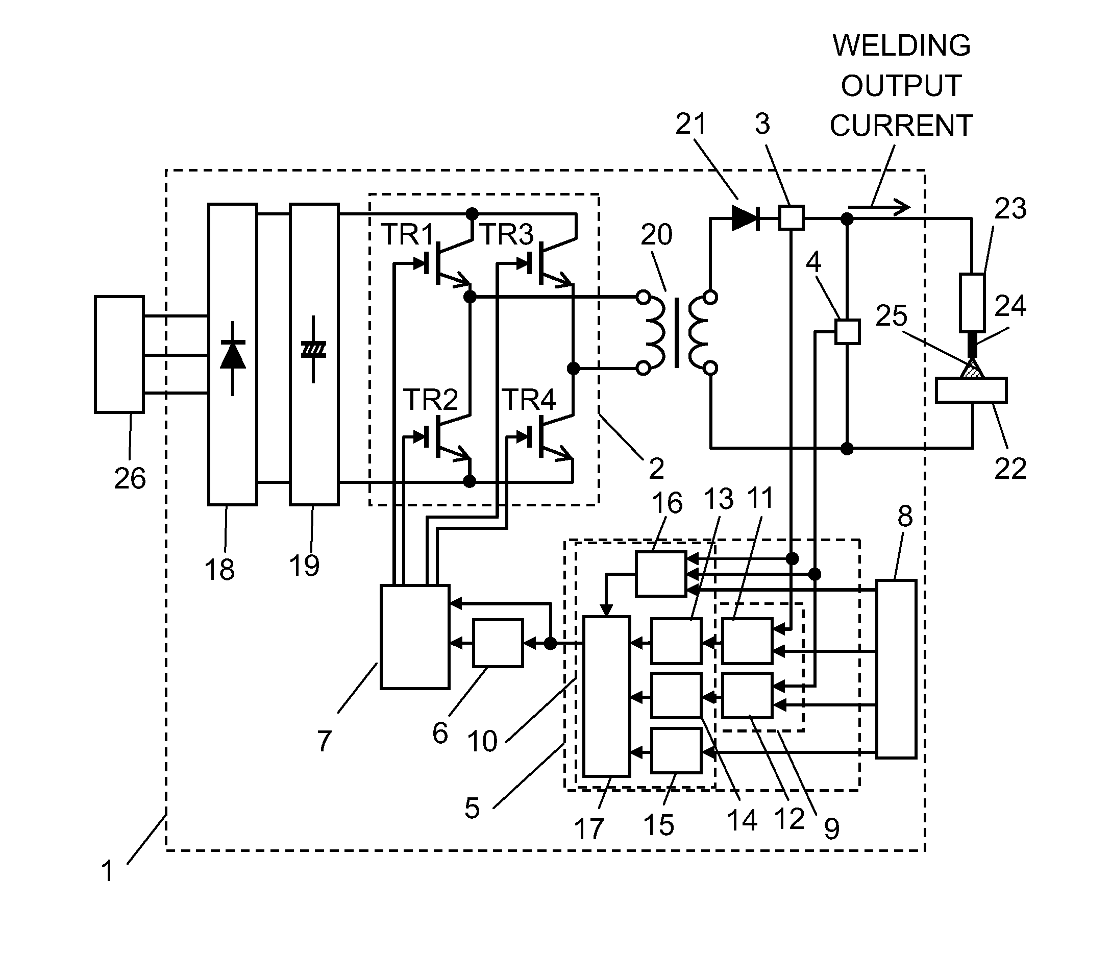
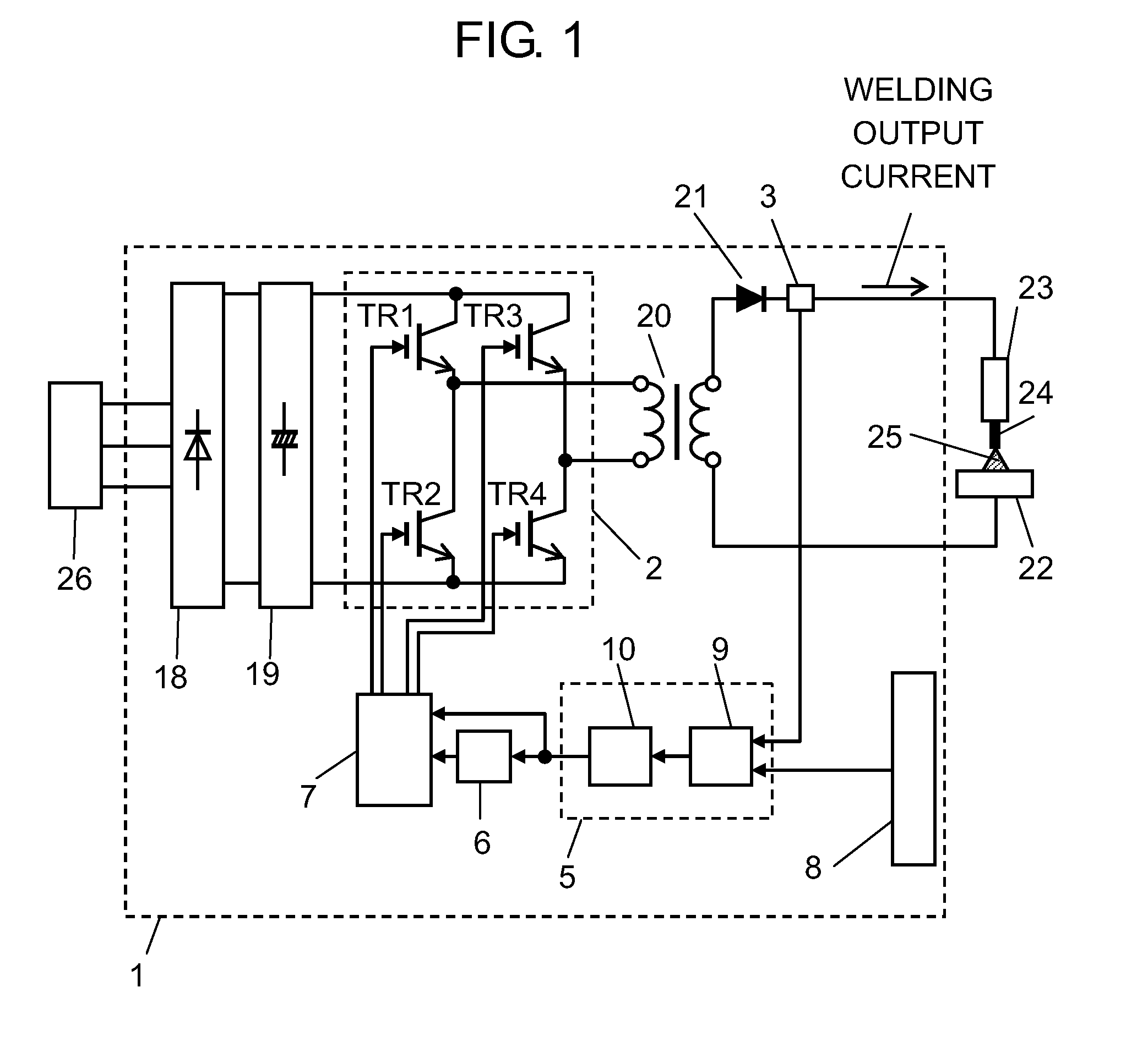
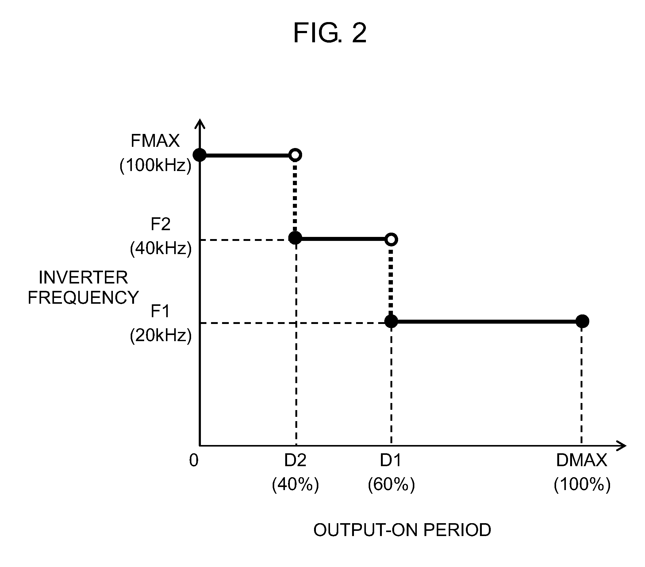
[0027]FIG. 1 schematically shows the structure of welding device 1 in accordance with the first exemplary embodiment. FIG. 2 is a graph showing that the inverter frequency changes stepwise in the output-on period of a welding device of the embodiment. FIG. 3 shows changes over time in the output-on period and driving timing of each switching element of the embodiment. FIG. 4 is a graph showing that the inverter frequency changes continuously in the output-on period of the embodiment.

[0028]As shown in FIG. 1, welding device 1 has primary rectifier 18, smoothing capacitor 19, switching section 2, transformer 20, secondary rectifier 21, current detector 3, setting section 8, controller 5, frequency controller 6, and driver 7. Switching section 2 has first switching element TR1, second switching element TR2, third switching element TR3, and fourth switching element TR4. Controller 5 has ...

exemplary embodiment 2

[0068]The structure of the second exemplary embodiment is described with reference to FIG. 5 and FIG. 6.

[0069]FIG. 5 schematically shows the structure of welding device 1 of the second exemplary embodiment. FIG. 6 shows a waveform of welding output and timing of a signal in short-circuiting arc welding of the embodiment.

[0070]In the structure of the embodiment, like parts are identified by the same reference marks as in the structure of the first exemplary embodiment, and detailed description thereof will be omitted. The structure of the second embodiment differs from that of the first embodiment in having voltage detector 4 and in the structure and workings of controller 5.

[0071]In FIG. 5, welding device 1 has voltage detector 4 for detecting welding voltage of device 1. In the description of the exemplary embodiment, current detector 3 and voltage detector 4 are collectively mentioned as the output detector. Controller 5 of welding device 1 has output comparator 9 and calculator 1...


PUM

PropertyMeasurementUnit
inverter frequency F2aaaaaaaaaa
frequency FMAXaaaaaaaaaa

Abstract

The welding device of the present disclosure has a switching section, a setting section, an output detector, a controller, a frequency controller, and a driver. The switching section is formed of a switching element. The setting section determines setting output. The output detector detects welding output. The controller calculates an output-on period of the switching section according to the setting output and the welding output. The frequency controller determines an inverter frequency based on the output-on period. The driver controls on/off operation of a switching element of the switching section based on the inverter frequency and the output-on period. When the output-on period is calculated using a first ratio, the inverter frequency is determined to a first frequency, and when the output-on period is calculated using a second ratio smaller than the first ratio, the inverter frequency is determined to a second frequency higher than the first frequency.

Description

TECHNICAL FIELD[0001]The present disclosure relates to a welding device that performs arc welding using inverter control.BACKGROUND ART[0002]Recently, the growing use of digital control and increase in speed of inverter frequencies allows a welding device working using inverter control to have welding output with various waveforms.[0003]Such a welding device performing arc welding using inverter control has an inverter circuit of a full-bridge structure or a half-bridge structure. Switching elements that form a bridge are power semiconductor devices, such as an IGBT (Insulated Gate Bipolar Transistor) and a MOSFET (Metal-Oxide Semiconductor Field Effect Transistor). Such a power semiconductor device is generally driven by inverter frequencies ranging from several kilohertz to 400 kilohertz, and controls the primary current conduction width of a transformer connected to an inverter circuit, so that welding output is obtained.[0004]As an inverter control method, a PWM (Pulse Width Mod...

Claims


Application Information

Patent Timeline
Patent Type & Authority Applications(United States)
IPC IPC(8): B23K9/073B23K9/10B23K9/095H02M3/335
CPCB23K9/073B23K9/095B23K9/1043H02M3/33515B23K9/09B23K9/0953B23K9/167B23K9/173H02M7/53871Y02P70/10
Inventor TANAKA, YOSHIAKITABATA, YOSHIYUKISHIMABAYASHI, SHINSUKE
Owner PANASONIC INTELLECTUAL PROPERTY MANAGEMENT CO LTD
Why Eureka
Try Eureka