
Continuous Downlinking While Drilling

a technology of continuous downlinking and drilling, applied in the field of downhole communication, can solve the problems requiring significant changes (modulation), and the known downlinking methods are generally slow, so as to improve the information available, enhance the directional drilling and steering control, and not to the effect of affecting the drilling process

Active Publication Date: 2016-05-26
SCHLUMBERGER TECH CORP
View PDF2 Cites 5 Cited by
  • Summary
  • Abstract
  • Description
  • Claims
  • Application Information

AI Technical Summary

Benefits of technology

The patent describes methods for improving drilling performance by allowing for continuous downlinking from the surface to the bit while drilling. This provides a stream of continuous parameter values, which can enhance the information available to the downhole tools. The methods use time-based, closed-loop methods for directional drilling and steering control, which can be further improved by downlinking a continuous rate of penetration to the bit. The methods are advantageous in that they don't significantly impact the drilling performance and can be used concurrently with other conventional downlinking methodologies. Additionally, the methods may enable data to be downlinked in analog form using continuous modulation, thereby substantially eliminating quantization errors.

Problems solved by technology

However, known downlinking methods (methods for transmitting information from the surface to the BHA) are generally slow (e.g., on the order of 1 to 2 bits per minute) and discontinuous (e.g., implemented when the drill bit is off bottom or to transmit a discrete command).
While conventional downlinking methods may be implemented while drilling, such an implementation tends to require significant changes (modulation) to the drilling fluid (mud) flow rate and / or the drill string rotation rate which can negatively impact the drilling process.
For example, significant changes to the mud flow rate may adversely affect bit cleaning, hole cleaning, directional capability, and BHA power generation.
Significant changes to the drill string rotation rate may adversely affect the rate of penetration and drill string dynamics (modes of vibration).
Electromagnetic telemetry methods may also sometimes be used; however, these methods can also have bandwidth limitations and may be limited to fields having suitable well depths and formation resistivity.

Method used


Image

  • Continuous Downlinking While Drilling
  • Continuous Downlinking While Drilling
  • Continuous Downlinking While Drilling

Examples


embodiment 100

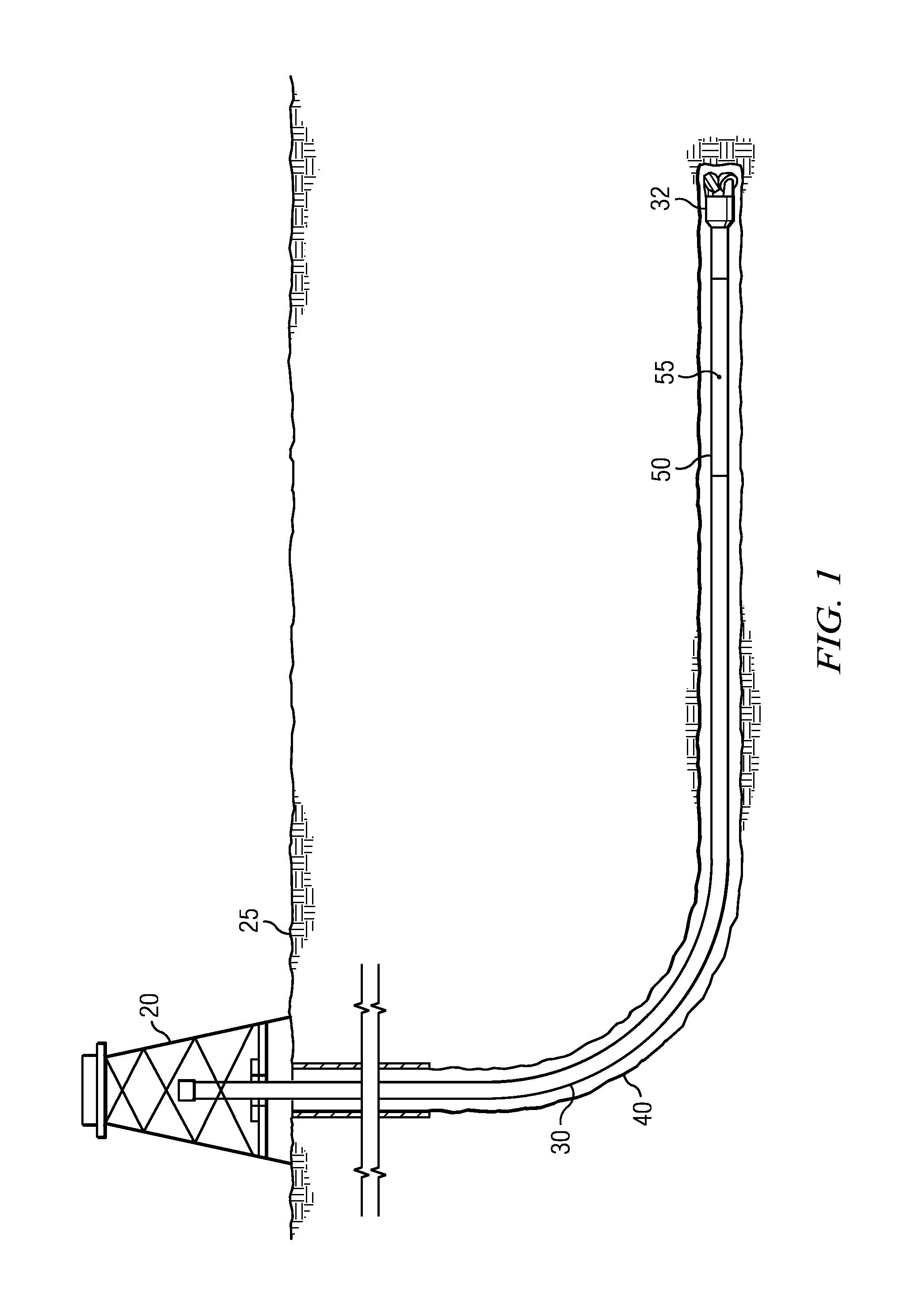
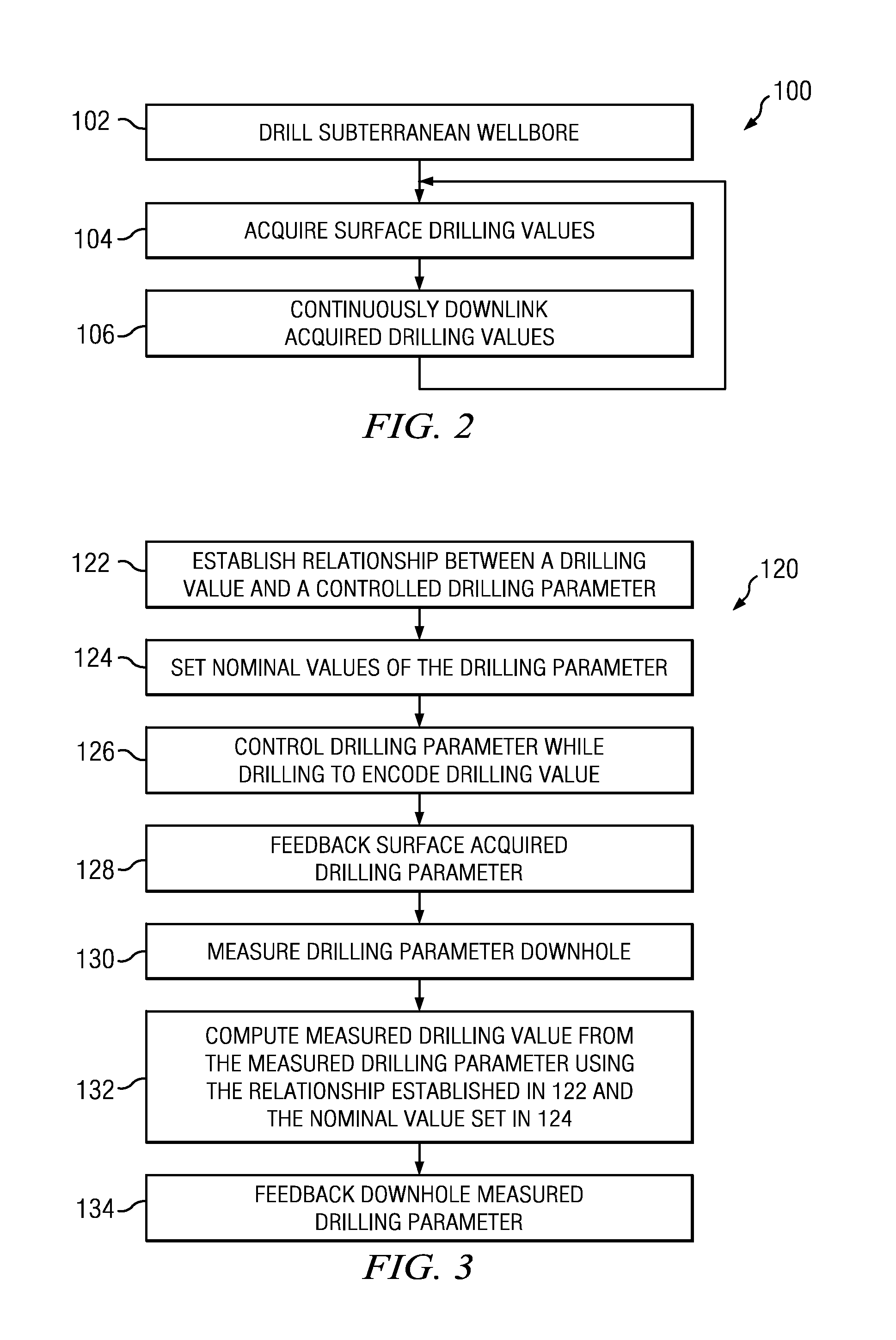
[0018]FIG. 2 depicts a flow chart of one disclosed method embodiment 100 for continuously downlinking drilling information from the surface to a downhole tool. A drill string (such as drill string 30 depicted on FIG. 1) is deployed in and used to drill a subterranean wellbore at 102, for example, via rotating the drill string and / or pumping drilling fluid downhole to power a mud motor. One or more drilling values are continuously acquired (e.g., measured, derived, or otherwise received) at the surface at 104 while drilling. The acquired drilling values may include, for example, weight on bit, rate of penetration, applied torque, measured depth, and the like. One or more of the acquired drilling values are downlinked from the surface to a downhole tool (or controller) at 106. The acquiring and downlinking are continuously repeated such that the acquired values are continuously downlinked (as depicted). By continuously acquired and continuously downlinked it is meant that the drilling...

embodiment 120

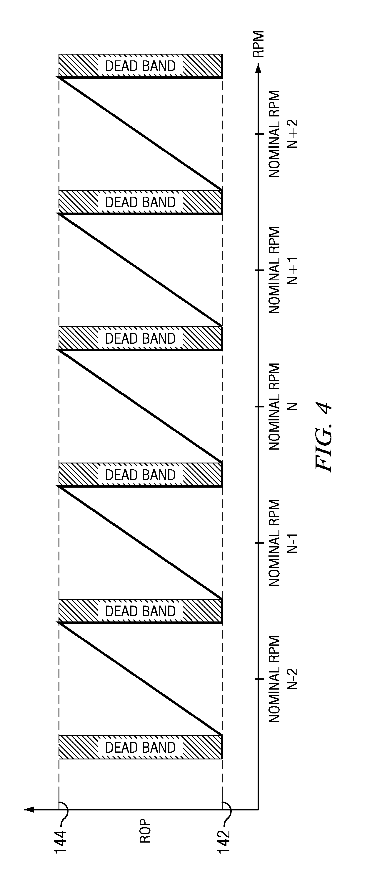
[0019]FIG. 3 depicts a flow chart of another disclosed method embodiment 120. At 122 a relationship is established between an input signal (e.g., the acquired drilling value) to be downlinked and a drilling parameter to be varied at the surface. The establishing relationship defines the drilling value as a repeating (e.g., a periodic) function of the drilling parameter. At 124 a nominal value of the drilling parameter is selected (set) based upon the details of the drilling operation and the drilling process being utilized. The nominal value may be, for example, the midpoint of a selected period of the established repeating function. The nominal value may be encoded at the surface prior to beginning the drilling operation or may be downlinked using conventional downlinking methods. While drilling the drilling parameter is controlled at 126 to encode the acquired drilling value based upon the relationship established in 122. The controlled drilling parameter may be measured at the su...

embodiment 160

[0027]FIG. 5 depicts a block diagram of still another example method embodiment 160 for continuously downlinking a drilling value such as ROP. In the depicted embodiment, steps that are performed uphole are indicated at 162 while steps performed downhole are indicated at 164. Method 160 is similar to method 120 in that a mathematical relationship is established between the ROP and ΔRPM at 166 (in which ΔRPM represents the deviation from the nominal RPM). The disclosed embodiments are not limited to ROP vs. RPM as described above. The desired RPM for the drilling operation is input into a nominal RPM planner at 168 to obtain a nominal RPM. The measured ROP may be filtered (e.g., time averaged) and input into downhole and surface loop ROP controllers at 170 and 172. The outputs may be summed (or averaged) at 174 and received at 166. The ΔRPM computed at 166 is combined (e.g., added) with the nominal RPM at 176 to obtain a controlled RPM for the top drive 178. The actual top drive rota...


PUM


Abstract

A method for continuous downlinking from a surface location to a bottom hole assembly includes using a bottom hole assembly to drill a subterranean wellbore. A drilling value is acquired at a surface location while drilling. The acquired drilling value is downlinked from the surface location to the bottom hole assembly. This process is continuously repeated while drilling.

Description

CROSS REFERENCE TO RELATED APPLICATIONS[0001]This application claims the benefit of U.S. Provisional Patent Application Ser. No. 62 / 082,496 entitled Continuous Downlinking While Drilling, which was filed on Nov. 20, 2014.FIELD OF THE INVENTION[0002]Disclosed embodiments relate generally to downhole communications and more particularly to methods for continuously downlinking information from the surface to a downhole tool while drilling.BACKGROUND INFORMATION[0003]Modern downhole drilling techniques may be enhanced via two-way communication between the surface and a bottom hole assembly (BHA). In many drilling operations digital data is continuously streamed from the BHA to the surface at data rates in a range from about 1 to about 20 bits per second (e.g., using mud pulse telemetry or a mud siren). However, known downlinking methods (methods for transmitting information from the surface to the BHA) are generally slow (e.g., on the order of 1 to 2 bits per minute) and discontinuous (...

Claims


Application Information

Patent Timeline
Patent Type & Authority Applications(United States)
IPC IPC(8): E21B44/02E21B44/06E21B3/00
CPCE21B44/02E21B44/06E21B3/00E21B44/00E21B47/12
Inventor PARKIN, EDWARD GEORGEBOGATH, CHRISTOPHER C.
Owner SCHLUMBERGER TECH CORP
Learn More