
High specific area composite foam and an associated method of fabrication

a composite foam and high specific area technology, applied in the field of composite foam, can solve the problems of affecting the overall properties of conventional filler-matrix composite foam, and losing the nano-scale properties in the agglomerated form

Active Publication Date: 2016-05-26
GENERAL ELECTRIC CO
View PDF3 Cites 7 Cited by
  • Summary
  • Abstract
  • Description
  • Claims
  • Application Information

AI Technical Summary

Benefits of technology

The patent text describes a method for creating a composite foam that includes a metal template and a conformal atomic-scale film that is a 3-dimensional interconnected structure. The metal template has sintered interconnects with non-spherical pores, and the conformal atomic-scale film has a similar structure with non-spherical pores. The composite foam can be used for various applications such as electronics and sensors. The technical effects of the patent text include the creation of a composite foam with a 3-dimensional interconnected structure and the use of a metal template and conformal atomic-scale film for various applications.

Problems solved by technology

However, overall properties of such filler-matrix composite foam are typically limited by the performance of interface regions of the filler-matrix.
The interface regions between the filler and the matrix typically present a very high thermal and electrical resistance respectively thereby affecting the overall properties of the conventional filler-matrix composites.
However, with conventional nano-scale fillers, there exist several practical limits to deposit filler within the matrix due to the tendency for nano-scale fillers to agglomerate, thereby losing their nano-scale properties in the agglomerated form.
Thus, the volume fraction of the nano-scale filler within the matrix is limited by processing-related limitations.

Method used


Image

  • High specific area composite foam and an associated method of fabrication
  • High specific area composite foam and an associated method of fabrication
  • High specific area composite foam and an associated method of fabrication

Examples


Embodiment Construction

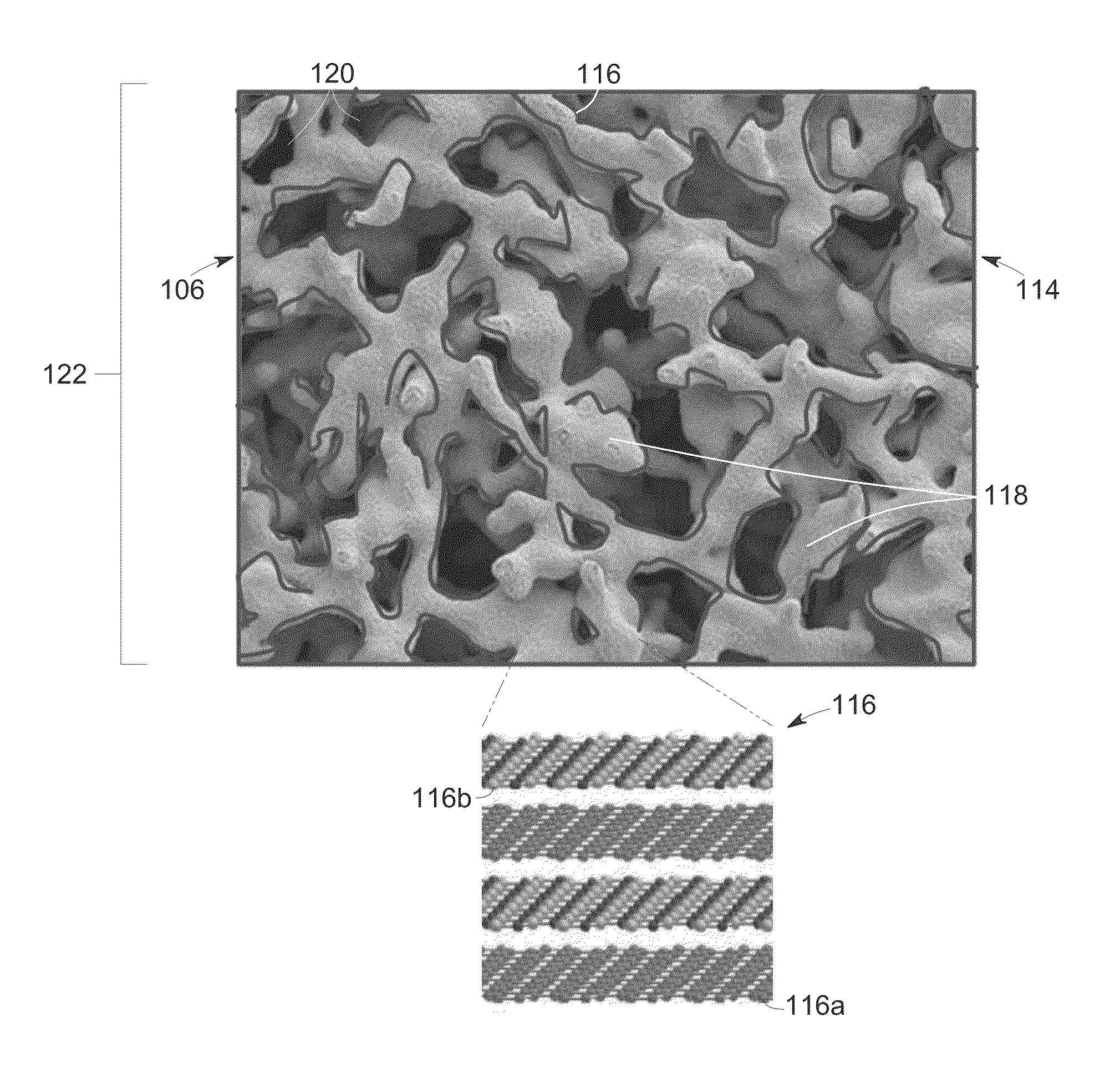
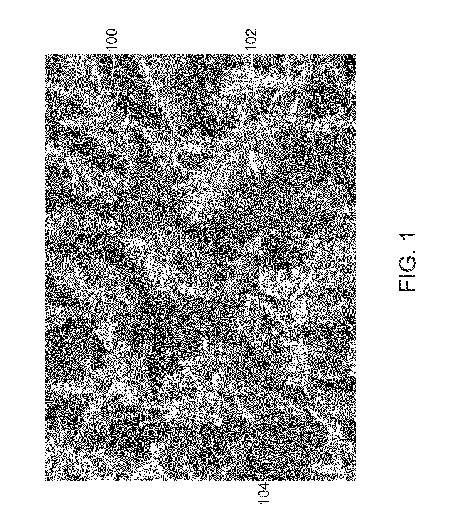
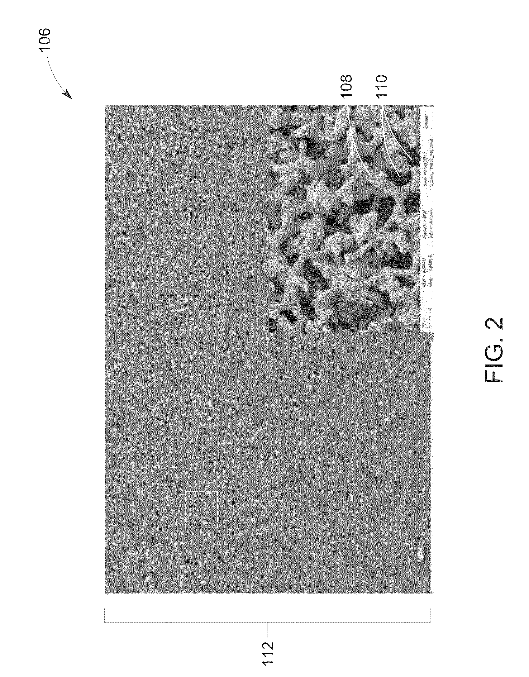
[0028]Embodiments discussed herein disclose a new composite foam for deployment in an electronics product, for example, as a thermal interface material and / or as a heat sink and / or as a heat spreader, and the like. Such composite foam provides a superior thermal, electrical and mechanical property to the underlying electronic product. In one embodiment of the present technology, the composite foam includes a metal template having high surface-area-to-volume ratio and a conformal atomic-scale film disposed directly over the metal template to form a 3-dimensional interconnected structure comprising the atomic-scale film. The metal template is formed by sintering a plurality of dendritic particles including a nickel and / or a copper of a suitable particle size distribution (PSD), at a controlled atmosphere to obtain the high surface-area-to-volume ratio. The conformal atomic-scale film, once deposited on the metal template, has an approximately equal surface-area-to-volume ratio as that...


PUM

PropertyMeasurementUnit
sizeaaaaaaaaaa
aspect ratioaaaaaaaaaa
sizeaaaaaaaaaa

Abstract

Composite foams are provided including a metal template and a conformal atomic-scale film disposed over such metal template to form a 3-dimensional interconnected structure. The metal template includes a plurality of sintered interconnects, having a plurality of first non-spherical pores, a first non-spherical porosity, and a first surface-area-to-volume ratio. The conformal atomic-scale film has a plurality of second non-spherical pores, a second non-spherical porosity, and a second surface-area-to-volume ratio approximately equal to the first surface-area-to-volume ratio. The plurality of sintered interconnects has a plurality of dendritic particles and the conformal atomic-scale film includes at least one of a layer of graphene and a layer of hexagonal boron nitride.

Description

BACKGROUND[0001]The present technology relates to a composite foam, and more particularly to the composite foam including a conformal atomic-scale film having a high surface-area-to-volume ratio.[0002]In an electronics packaging industry, composite foams are typically used for providing at least one of a thermal, an electrical, and a mechanical property to an underlying electronic product and / or to one or more components used to build the electronics product.[0003]Such composite foams used for a thermal management application may include a matrix and a nano-scale fillers deposited within the matrix. Generally, the fillers deposited within the matrix form multiple islands with no direct interconnection between the fillers. The composite foam may be made of a single layer or multiple layers of the matrix material to provide a macro-scopic structure to the composite foam.[0004]Typically, individual fillers provide thermal and electrical property enhancements, and the matrix provides me...

Claims


Application Information

Patent Timeline
Patent Type & Authority Applications(United States)
IPC IPC(8): F28F21/02F28F21/06B22F1/054
CPCY10T428/249958Y10T428/249955F28F21/067F28F21/02Y10T428/249978B22F7/00F28F13/003F28F21/00H01L23/3733F28F2255/18B22F2998/10B22F7/02B22F3/24B22F3/114B22F3/1115B22F3/11B22F3/1137B22F1/0553B22F1/054B22F1/056B22F3/10B22F2003/244B22F3/26B22F2007/045
Inventor CHAUHAN, SHAKTI SINGHNAGARKAR, KAUSTUBH RAVINDRAMISNER, MATTHEW JEREMIAHAHMAD, FAISAL RAZI
Owner GENERAL ELECTRIC CO
Learn More