Biocompatible electrode structure and method for manufacturing the same, and device and method for manufacturing the same

a biocompatible electrode and electrode technology, applied in the field of biocompatible electrode structure and manufacturing method, can solve the problems of insufficient advanced understanding of the influence of conductive nanomaterial such as carbon nanotube (cnt) on the living body, damage to the original softness of the polymeric medium, and inability to study the use of conductive nanomaterial such as carbon nanotube (cnt) as a material of the device installed on the surface of the living body or in the body, etc., to achieve high accuracy ratio ratio ratio ratio ratio ratio ratio ratio ratio ratio ratio ratio ratio ratio ratio ratio ratio ratio ratio ratio ratio ratio ratio ratio

Active Publication Date: 2016-06-02
JAPAN SCI & TECH CORP
View PDF5 Cites 29 Cited by
  • Summary
  • Abstract
  • Description
  • Claims
  • Application Information

AI Technical Summary

Benefits of technology

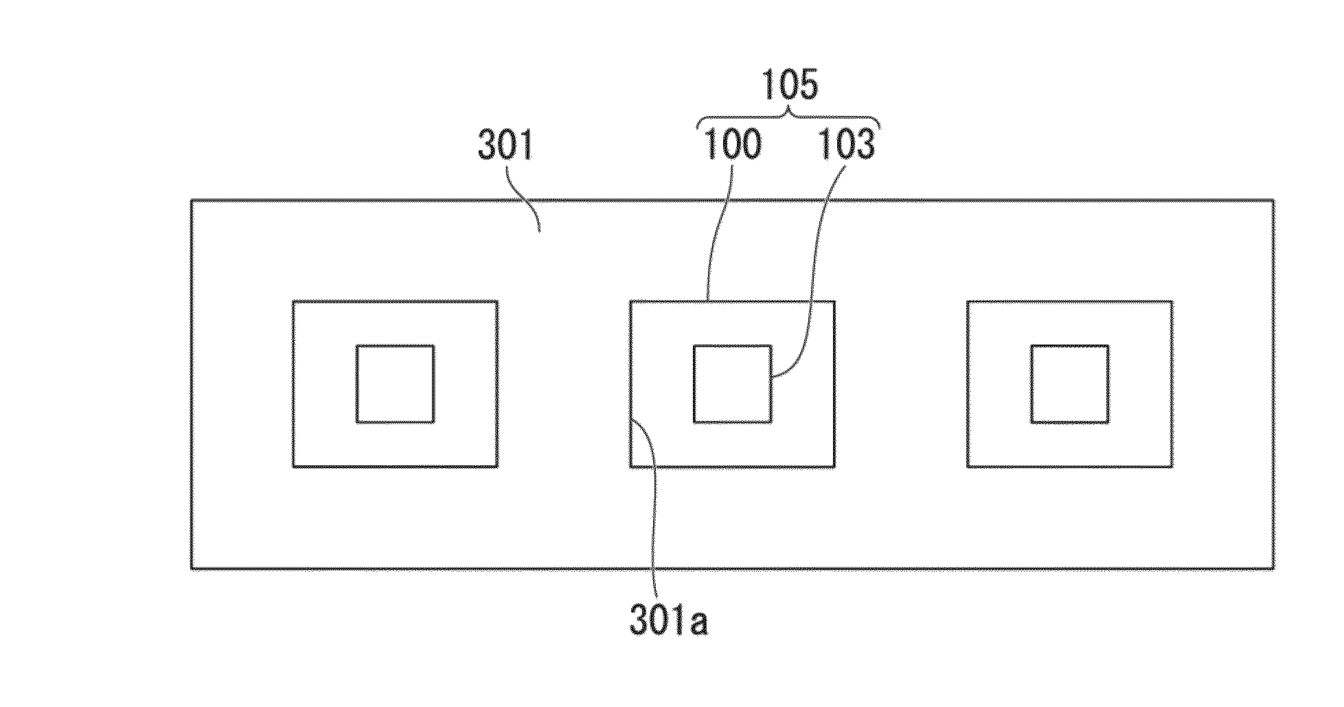
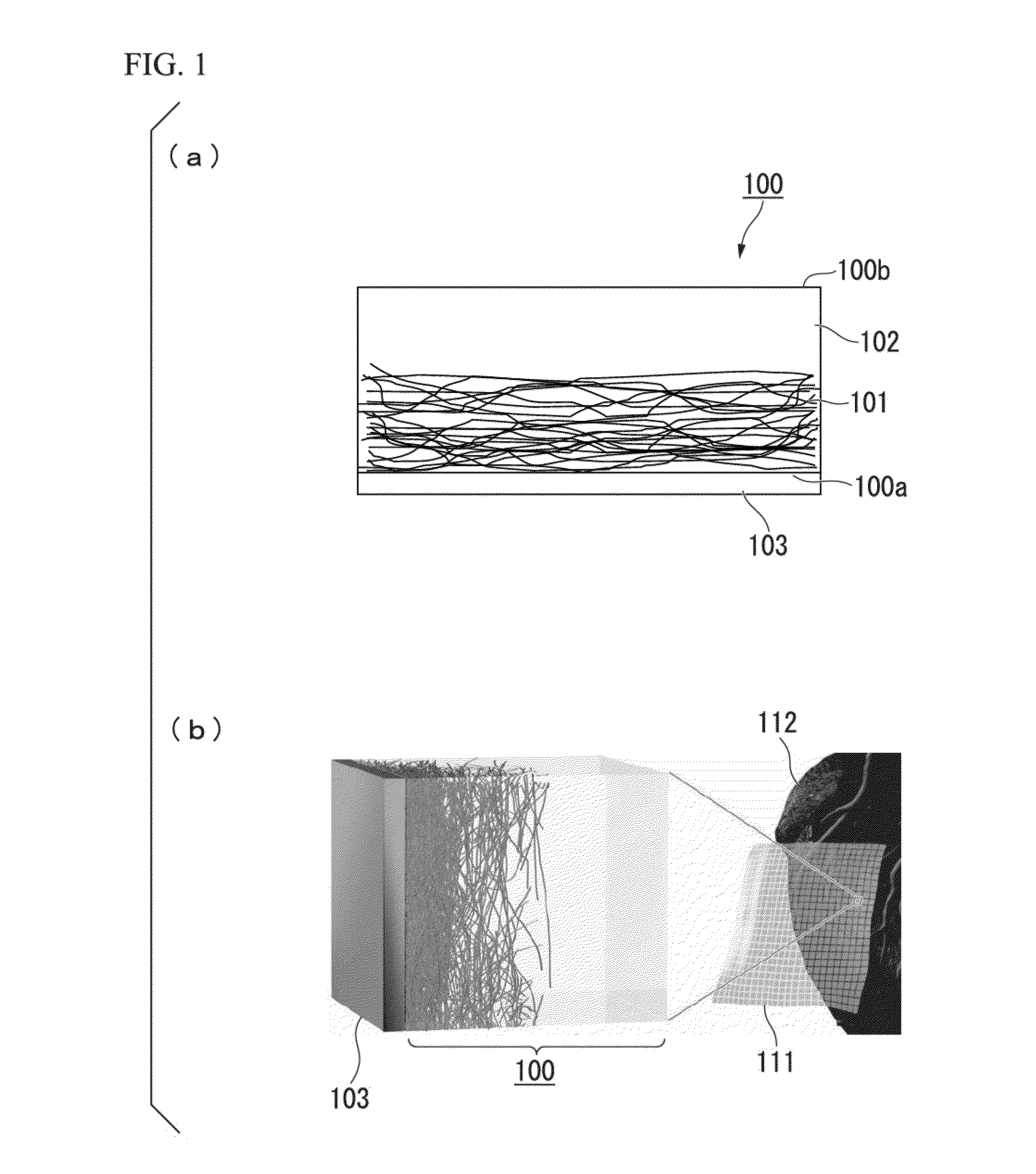
[0035]In this manner, the biocompatible electrode structure of the present invention can be used as a material of the electrode for a living body where the antibody response is small at the time of being put into the living body for the long period, and reliability is high. Moreover, since the biocompatible electrode structure of the present invention is very soft, it is possible to cover the surface of a biological tissue, without hurting the biological tissue. Still more, there is a cell tissue of approximately several 100 μm, but since the biocompatible electrode structure of the present invention can perform photocrosslinking, it is possible to manufacture a fine electrode of a size which may be applied to a predetermined cell tissue.
[0036]Additionally, the electrode which is manufactured by the biocompatible electrode structure of the present invention, can stably read out the signal of the internal organ for the long period by being stuck to the internal organ or the like in the living body. If a weak signal from the living body is not amplified, the detection is difficult, but by including a soft amplifier that is manufactured by using an organic transistor (for example, NATURE MATERIALS, 9, 2010, 1015 to 1022) near the internal organ, it is possible to amplify the electrical signal from the internal organ or the like. Thereby, it is possible to bring out a very weak electrical signal with high accuracy, and it is possible to detect the weak signal from the living body.
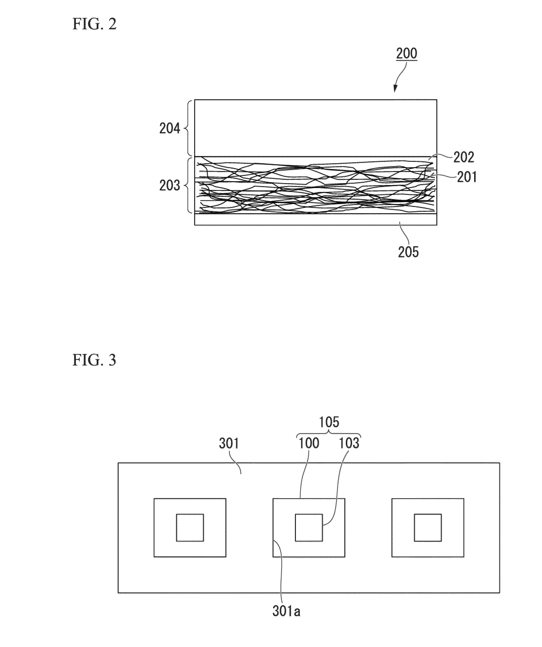
[0037]According to the method for manufacturing the biocompatible electrode structure according to the aspect of the present invention, since a configuration including the process of collectively processing the first polymeric medium that constitutes the first polymer layer which includes the conductive nanomaterial, and the second polymeric medium that constitutes the second polymer layer which does not include the conductive nanomaterial or includes the conductive nanomaterial at the density which is lower than that of the first polymer layer so as to be arranged on each electrode is adopted, it is possible to easily adjust the impedance of the biocompatible electrode structure only by changing the density of the conductive nanomaterial or a thickness of the polymer layer.

Problems solved by technology

However, the understanding of an influence which the conductive nanomaterial such as the carbon nanotube (CNT) has on the living body is not sufficiently advanced, and the study of using the conductive nanomaterial such as the carbon nanotube (CNT) as a material of the device which is installed onto the surface of the living body or in the body is not advanced.
Additionally, a material dispersing the conductive nanomaterial into a polymeric medium is a material that has both of softness of the polymeric medium and conductivity of the conductive nanomaterial, but in a portion where the conductive nanomaterial is included, the original softness of the polymeric medium is damaged.
Moreover, if the conductive nanomaterial is largely included in a portion which is in contact with the living body, there is a case where an inflammatory response occurs.
On the other hand, if the conductive nanomaterial is small, there is a problem in that the impedance between the electrode and the device becomes large, or exchange of the information with good accuracy is not possible.

Method used


Image

  • Biocompatible electrode structure and method for manufacturing the same, and device and method for manufacturing the same
  • Biocompatible electrode structure and method for manufacturing the same, and device and method for manufacturing the same
  • Biocompatible electrode structure and method for manufacturing the same, and device and method for manufacturing the same

Examples


examples

[0167]FIG. 4(a) is a photograph showing the state before the composition that is made by dispersing the carbon nanotube which is covered with the molecules configuring N,N-diethyl-N-methyl-N-(2-methoxyethyl)ammonium tetrafluoroborate (DEMEBF4) into polyrotaxane is cured by ultraviolet rays (UV). It is found out that the obtained composition has a gel shape. In the present specification. “gel shape” is a designation with respect to a liquid shape having fluidity, and means a state where the fluidity is lost, or a state where the fluidity is substantially lost.

[0168]The biocompatible electrode structure according to the present invention may be manufactured by using the composition. That is, the composition is applied on the electronic circuit, and the carbon nanotube is unevenly distributed using a magnet from below, and it is possible to manufacture a biocompatibility electrode structure by curing that. Moreover, the composition is applied on the electronic circuit, and thereon, a l...


PUM

PropertyMeasurementUnit
sizeaaaaaaaaaa
widthaaaaaaaaaa
diameteraaaaaaaaaa

Abstract

There is provided a biocompatible electrode structure which is capable of being connected to an electronic circuit, and in which a conductive nanomaterial is dispersed into a polymeric medium, in which a density of the conductive nanomaterial on an opposite side of a connection surface to the electronic circuit, in the polymeric medium is lower than that on the side of the connection surface to the electronic circuit.

Description

BACKGROUND OF THE INVENTION[0001]1. Field of the Invention[0002]The present invention relates to a biocompatible electrode structure and a method for manufacturing the same, and a device and a method for manufacturing the same.[0003]Priority is claimed on Japanese Patent Application No. 2013-149663, filed Jul. 18, 2013, the content of which is incorporated herein by reference.[0004]2. Description of Related Art[0005]Flexible electronics using an organic semiconductor have received attention in recent years, as means for installing a device that is configured by a soft material onto a surface or an inside of a living body, and obtaining biological information directly from a cell or a tissue. On the inside of the living body, an electrical contact with the tissue or the cell is mainly performed through metal such as Pt or Au (NPL 1 or NPL 2).[0006]However, if the metal such as Pt or An is in contact directly with the tissue or the cell of the living body, since inflammatory response ...

Claims


Application Information

Patent Timeline
Patent Type & Authority Applications(United States)
IPC IPC(8): H01B1/24H05K1/09A61L31/12A61B5/296
CPCH01B1/24A61L31/126A61L2400/12A61L2420/02A61L2420/04H05K1/09A61L27/50A61B5/6846A61B5/6867A61B5/686A61B2562/0214
Inventor SOMEYA, TAKAOSEKITANI, TSUYOSHITAKANO, REMI
Owner JAPAN SCI & TECH CORP
Why Eureka
Try Eureka