Beamforming method, measurement and imaging instruments, and communication instruments

a beamforming and beam technology, applied in the field of beams, can solve the problems of reducing the spatial resolution of signals, reducing the sampling frequency of ad converters, and ad converter sampling frequency too high with a high cost, and achieve high speed, high accuracies, and high speed

Active Publication Date: 2016-06-09
CHIKAYOSHI SUMI
View PDF3 Cites 155 Cited by
  • Summary
  • Abstract
  • Description
  • Claims
  • Application Information

AI Technical Summary

Benefits of technology

[0096]According to one of viewpoints of the present invention, it is made possible, while using instruments with digital operational functions as digital beamformers, to perform arbitrary beamformings with high speeds and high accuracies with no approximate calculations. As explained later in detail, the present invention realizes, on the basis of proper using of the multiplications of complex exponential functions and the Jacobi operation, arbitrary beamformings on arbitrary orthogonal coordinate systems including a curvilinear coordinate system with high speeds and high accuracies with no approximate interpolations.
[0097]Although the DAS (Delay and Summation) processing realizes arbitrary beamformings including conventional beamformings, when using a 1D array-type physical aperture and a general PC (personal computer), at least the present invention makes the calculation speeds 100 times as high as those achieved using the DAS processing. When the aperture elements distribute in a 2D or 3D space or comprise a multidimensional array, the present invention efficiently solve the problem that it takes more processing times in the multidimensional cases than in the 1D case, i.e., the increasing the speediness of beamforming becomes more efficient.
[0098]That is, the present invention uses a transmission or reception transducer array device with an arbitrary aperture geometry (it may be used for both transmission and reception) or a sensor array device, and allows arbitrary beamformings with high speeds and high accuracies and with no approximate interpolations via digital processing. In practical, arbitrary focusings, arbitrary steerings, arbitrary apodizations can be performed with array devices with arbitrary aperture geometries.
[0099]For instance, in a field of medical ultrasound imaging, according to observation targets, a coordinate system on which physical transmission and reception and digital sampling are performed is selected such as a Cartesian coordinate system for a linear array-type transducer and a polar coordinate system popular for a convex type transducer, a sector scan, or an IVUS (intravascular ultrasound). For instance, for observing a heart dynamics between ribs, the sector scan is performed generally. An aperture of not a transducer with an array-type aperture geometry but a PVFD (polyvinylidene fluoride) based transducer may be deformable. That is, the present invention allows obtaining signals directly beamformed on arbitrary coordinate systems such as image displays etc. with no approximate interpolations by processing digital signals obtained from waves transmitted and received on arbitrary coordinate systems.
[0100]For the multistatic SA, echo data frames with the number of reception elements are made from echo signals received at a same position within plural reception positions with respect to a transmission position, each of which echo data frame are processed by the monostatic SA of the present invention and finally the IFFT is implemented on the superposition of all the monostatic SA results. That is, echo data can be generated by performing the monostatic SA processings with the same number as that of received channels. Thus, it takes shorter time to complete the beamforming (a higher speed) than the DAS method, known as the general multistatic type method, that yields high spatial resolution image signals by generating low spatial resolution image signals to be superposed.
[0101]And on the basis of the multistatic processing of the present invention, the reception dynamic focusing and steering can also be performed, with respect to the popular fixed transmission focusing, with a high speed and a high accuracy. All the beamformings can be achieved by implementing the proper phase rotation processings using the multiplications of complex exponential functions.

Problems solved by technology

However, when signal energy is obtained, but on the other hand, the object movement with the deformation, and the object displacement and strain etc. decrease the spatial resolution of signals, and therefore, the measurement accuracy is decreased as well.
When implementing a digital delay for a transmission delay, an error determined by a clock frequency that generates a digital control signal, which is different from when performing an analogue delay.
Alternatively, because for performing a reception dynamic focusing, when implementing a digital delay on to a received signal, an error is caused by the above-mentioned interpolation approximation, the sampling frequency of an AD converter is made sufficiently high with a high cost, or the above-mentioned high accuracy digital delay (phase rotation processing) must be implemented, which leads to a low speed beamforming.
Such beamformings are much faster than the high accuracy phasing and summing using complex exponential functions, but, the accuracy is lower than that of the high accuracy phasing and summing.
However, any digital processing for steering and a multistatic SA (receptions using plural elements, generally, including a transmission element and the surrounding elements) has not been disclosed yet.
As mentioned above, although such digital beamforming has already had a long history, because in a case where a real-time processing up to displaying an image is made much of, approximate interpolations are often performed, the highest accuracy is not always provided.

Method used


Image

  • Beamforming method, measurement and imaging instruments, and communication instruments
  • Beamforming method, measurement and imaging instruments, and communication instruments
  • Beamforming method, measurement and imaging instruments, and communication instruments

Examples


1st embodiment

The 1st Embodiment

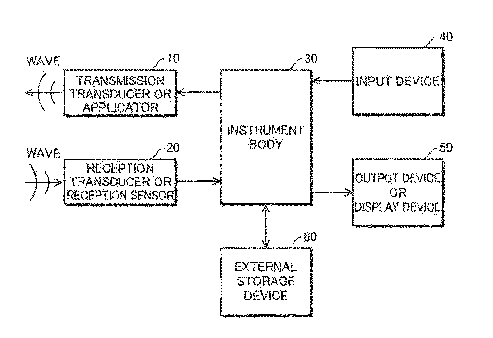
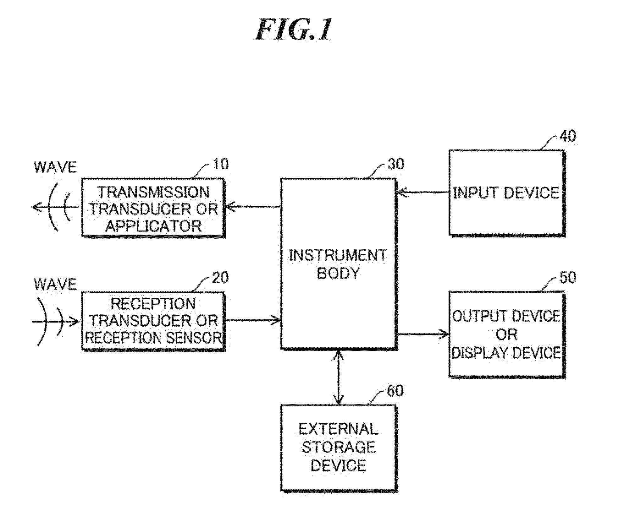
[0149]At first, the compositions of the measurement and imaging instrument or the communication instrument related to the first embodiment of the present invention are explained. FIG. 1 shows a schematic representation (block map) of compositions of the measurement and imaging instrument or the communication instrument related to the first embodiment of the present invention. As shown in FIG. 1, the measurement and imaging instrument (or communication instrument) is equipped with a transmission transducer (or an applicator) 10, a reception transducer (or a reception sensor) 20, an instrument body 30, an input device 40, an output device (or a display device) 50, and an external storage (memory) device 60.

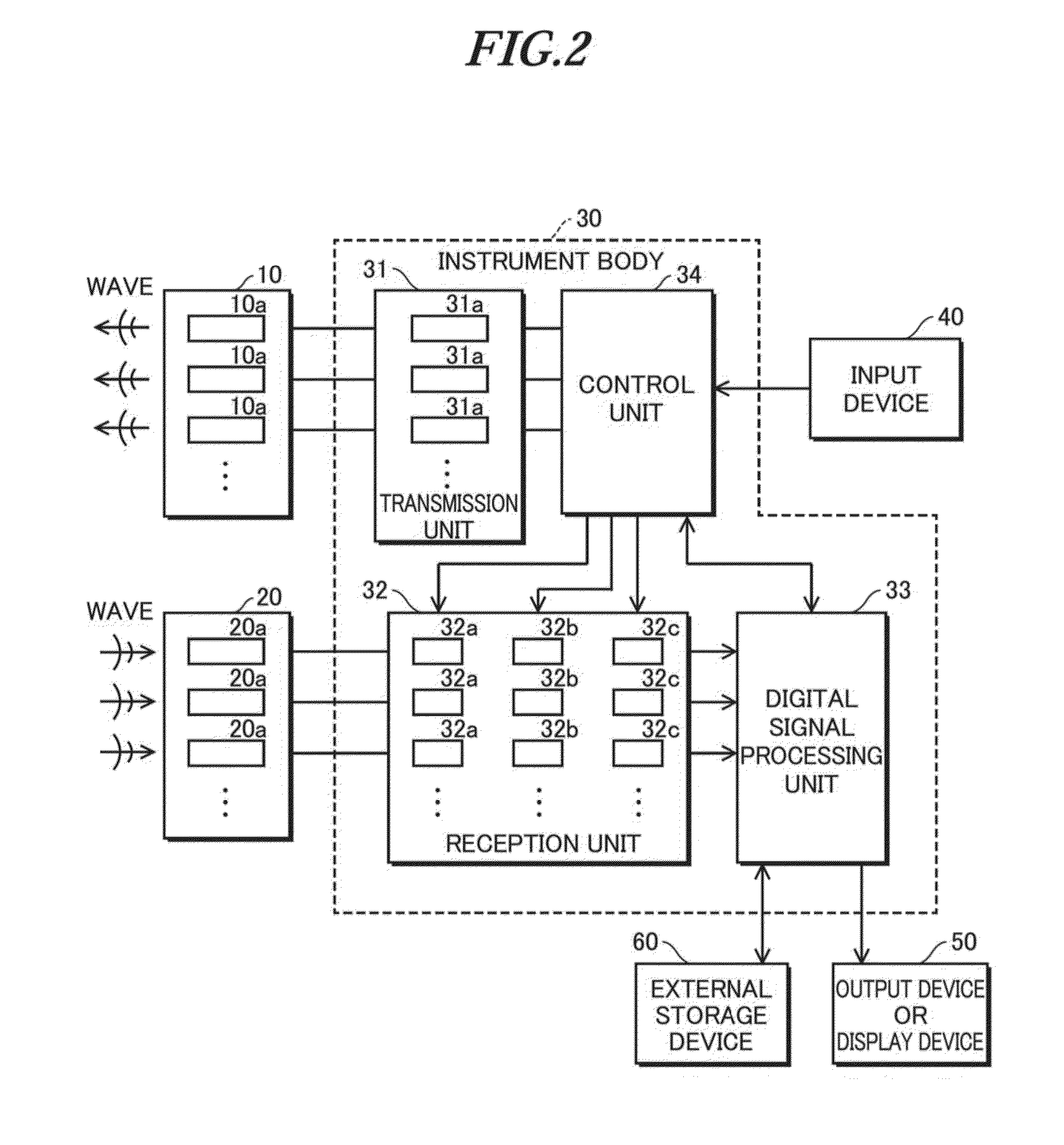
[0150]FIG. 2 shows the specific schematic representation (block map) of compositions of a body of instrument shown in FIG. 1. Mainly, the body of instrument 30 is equipped with a transmission unit 31, a reception unit 32, a digital signal processing unit 33 and a c...

2nd embodiment

[0613]Next, the compositions of the measurement and imaging instrument or the communication instrument related to the second embodiment of the present invention are explained. FIG. 1 shows a schematic representation (block map) of compositions for the active-type of instrument related to the first embodiment of the present invention; and FIG. 2 shows the specific schematic representation (block map) of compositions of a body of instrument shown in FIG. 1. In the second embodiment of the present invention, passive-type of instruments are used. Thus, at least the instruments related to the second embodiment are equipped with no transmission transducers and neither wire lines nor wireless lines for transferring drive signals from the control unit to the transmission transducers.

[0614]Regarding the active-type instrument related to the first embodiment, referring to FIGS. 1 and 2 showing a schematic representation (block map) of compositions of instrument, the compositions of the units ...

3rd embodiment

[0674]Being dependent on a frequency, a bandwidth, an intensity or a mode etc, the waves such as electromagnetic waves, lights, mechanical vibrations, acoustic waves or thermal waves exhibit different behaviors. As far, many transducers for various type waves are developed and the waves' transmission waves, reflection waves or scattering waves are used for imaging. For instance, it is well known that on non-destructive examinations, medicines or sonars, ultrasounds, i.e., acoustic waves with higher frequencies, are used. Also on radars, electromagnetic waves with proper frequencies with respect to observation objects are used such as microwaves, terahertz waves, infrared rays, visible waves or radioactive rays such as an X-ray etc. These are also for other waves.

[0675]On the imagings using such waves, amplitude data obtained via the quadrature detection, the envelope detection or the square detection are displayed in a gray or color scale in a 1D, 2D or 3D. Alternatively, on the Dop...


PUM

PropertyMeasurementUnit
wavenumberaaaaaaaaaa
frequencyaaaaaaaaaa
carrier frequencyaaaaaaaaaa

Abstract

Beamforming method that allows a high speed and high accuracy beamforming with no approximate interpolations. This beamforming method includes step (a) that generates reception signals by receiving waves arrival from a measurement object; and step (b) that performs a beamforming with respect to the reception signals generated by step (a); and step (b) including without performing wavenumber matching including approximate interpolation processings with respect to the reception signals, and the reception signals are Fourier's transformed in the axial direction and the calculated Fourier's transform is multiplied to a complex exponential function expressed using a wavenumber of the wave and a carrier frequency to perform wavenumber matching in the lateral direction and further, the product is Fourier's transformed in the lateral direction and the calculated result is multiplied to a complex exponential function, from which an effect of the lateral wavenumber matching is removed, to perform wavenumber matching in the axial direction, by which an image signal is generated.

Description

CROSS-REFERENCE TO RELATED APPLICATION[0001]The present application claims priority from Japanese Patent Applications No. 2014-116949 filed on Jun. 5, 2014 (inventor: Dr. Chikayoshi Sumi, an associate professor at Sophia University, Tokyo Japan), No. 2014-165284 filed on Aug. 14, 2014 (inventors: Dr. Chikayoshi Sumi and Mr. Naoto Yamazaki, a master degree student at Sophia University, Tokyo Japan), No. 2015-046528 filed on Mar. 9, 2015 (Dr. Chikayoshi Sumi), No. 2015-087901 filed on Apr. 22, 2015 (Dr. Chikayoshi Sumi), and No. 2015-106798 filed on May 26, 2015 (Dr. Chikayoshi Sumi), the contents of which are incorporated herein by reference in their entirety.BACKGROUND OF THE INVENTION[0002]1. Field of the Invention[0003]The present invention relates to beamforming methods that are used for beamforming on arbitrary waves that arrive from measurement objects. The present invention also relates to measurement and imaging instruments, and communication instruments using such beamformin...

Claims


Application Information

Patent Timeline
Patent Type & Authority Applications(United States)
IPC IPC(8): A61B8/08G01N29/46
CPCA61B8/5207G01N2291/02475G01N29/46A61B8/12A61B8/4494A61B8/54G01N29/0654G01N29/262G01S7/52047G01S15/8915G01S15/8927G01S15/8977G01S15/8997G10K11/32G10K11/341G10K11/346
Inventor SUMI, CHIKAYOSHIYAMAZAKI, NAOTO
Owner CHIKAYOSHI SUMI
Why Eureka
Try Eureka