Vehicle brake system

Active Publication Date: 2016-06-09
ADVICS CO LTD
View PDF1 Cites 6 Cited by
  • Summary
  • Abstract
  • Description
  • Claims
  • Application Information

AI Technical Summary

Benefits of technology

[0020]In the vehicle system, the control device preferably performs the reallocation control of reducing the reallocation start speed and increasing the decrease gradient of the regeneration braking force in the first period as the state of charge of the battery is lower. This configuration allows the reallocation start speed to be reduced as the state of charge is higher and the start time point of the reallocation control can thus be delayed regardless of whether or not the state of charge is not less than the predetermined amount. The decrease gradient of the regeneration braking force in the first period is made greater as the reallocation start speed is lower, in other words, the state of charge is lower. Even if the reallocation start speed and the decrease gradient of the regeneration braking force in the first period are changed in accordance with the state of charge, the decrease gradient of the regeneration braking force in the second period is not changed. As the state of charge is lower, the battery can be charged more efficiently as well as deterioration in drivability is restrained.
[0021]The control device preferably performs the reallocation control of setting the reallocation start speed to a fixed value, increasing the decrease gradient of the regeneration braking force in the first period and decreasing the decrease gradient of the regeneration braking force in the second period as the state of charge of the battery is higher. This configuration enables the decrease gradient of the regeneration braking force in the second pe

Problems solved by technology

Regeneration braking force applied from the regeneration brake device to the vehicle is harder to control than hydraulic br

Method used


Image

  • Vehicle brake system
  • Vehicle brake system
  • Vehicle brake system

Examples


first embodiment

[0041]A vehicle brake system according to a first embodiment will now be described below with reference to FIGS. 1 to 10. It is assumed in the following description herein that the vehicle travels (advances) forward (ahead of the vehicle).

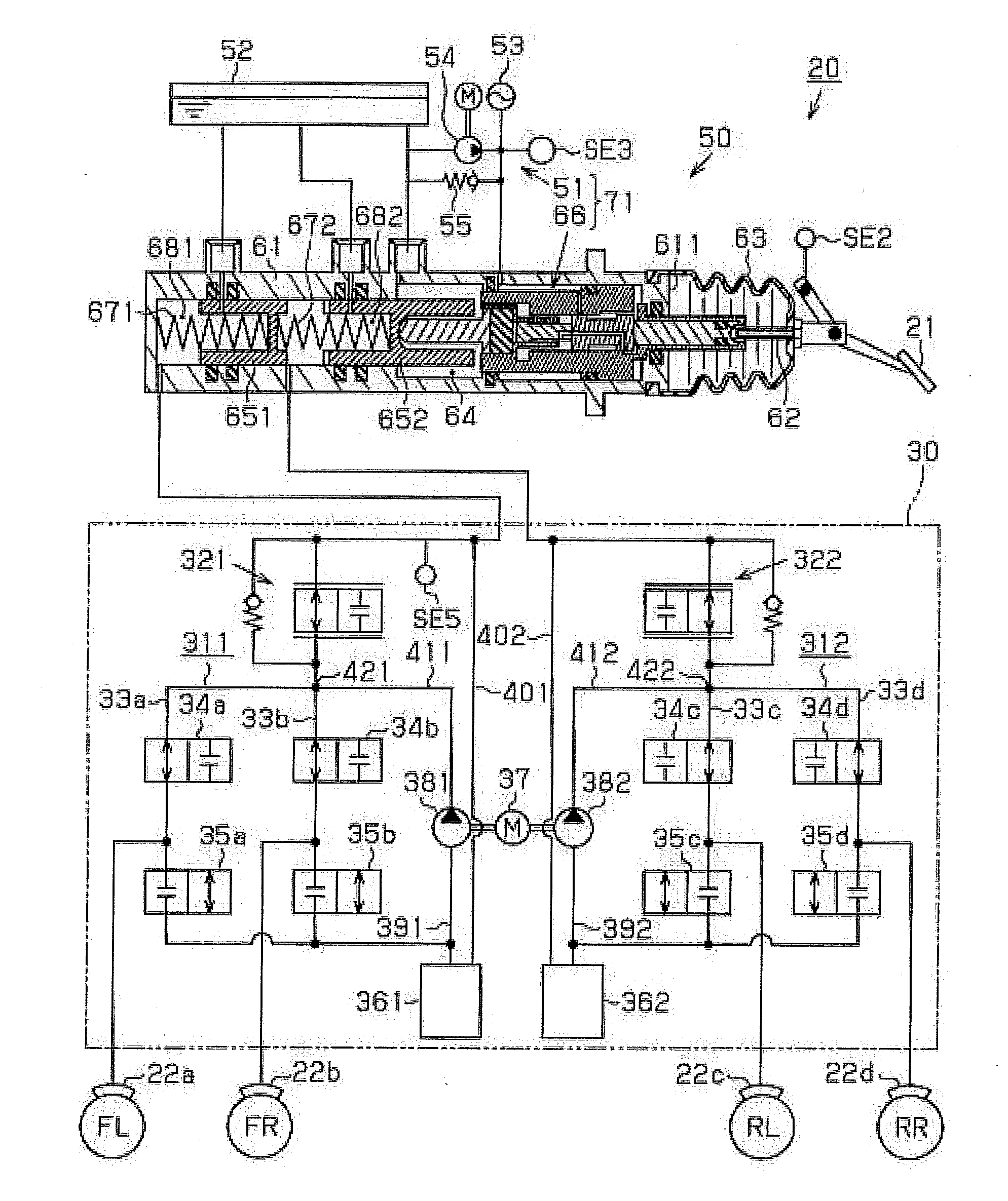
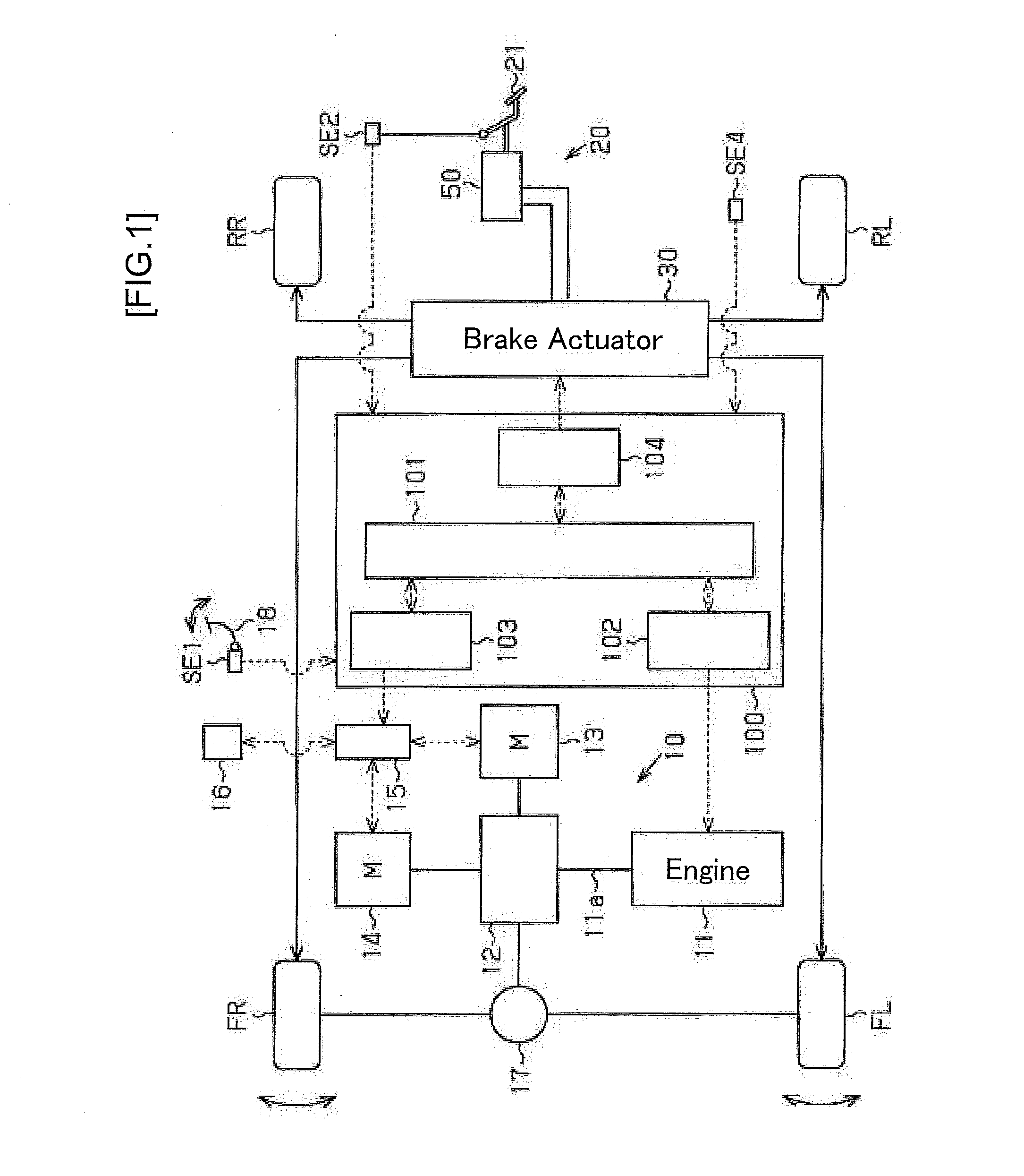
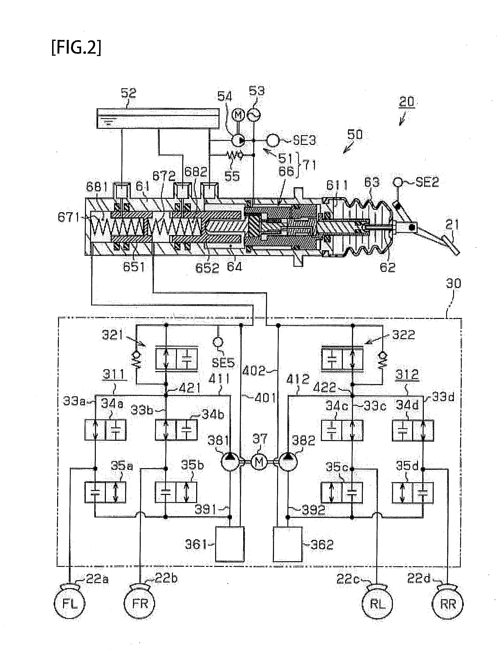
[0042]FIG. 1 depicts a hybrid vehicle including the brake system according to the present embodiment. As depicted in FIG. 1, the hybrid vehicle includes a two-motor hybrid system 10, a hydraulic brake device 20 configured to apply braking force (hydraulic braking force) to all wheels FL, FR, RL, and RR, and a control device 100 configured to totally control the vehicle.

[0043]The hybrid system 10 includes an engine 11 operated by supplied fuel such as gasoline. The engine 11 has a crank shaft 11 a that is coupled to a first motor 13 and a second motor 14 via a power transmission mechanism 12 having a planetary gear mechanism and the like. The power transmission mechanism 12 divisionally transmits motive power from the engine 11 to the first motor 13...

second embodiment

[0131]A vehicle brake system according to a second embodiment will be described next with reference to FIGS. 11 and 12. The brake system according to the second embodiment includes a booster device configured differently from that of the first embodiment. The following description will mainly refer to the differences from the first embodiment and will not repeatedly refer to the members configured identically to those of the first embodiment, which are denoted by the identical reference signs.

[0132]FIG. 11 depicts a basal fluid pressure supply device 50A included in the hydraulic brake device 20. As depicted in FIG. 11, provided between a master cylinder 61A and the brake pedal 21 is a booster device 71A of the negative pressure type. The booster device 71A includes a booster shell 120 fixed at a position shifted in the canceling direction −X from the master cylinder 61A. The booster shell 120 includes a front shell 121 on a side in the operating direction +X and a rear shell 122 on...

third embodiment

[0155]A vehicle brake system according to a third embodiment will be described next with reference to FIGS. 13 and 15. The brake system according to the third embodiment is different from those of the first and second embodiments in a method of changing the details of the reallocation control in accordance with the state of charge SOC of the battery 16. The following description will mainly refer to the differences from the first and second embodiments and will not repeatedly refer to the members configured identically to those of the first and second embodiments, which are denoted by the identical reference signs.

[0156]Initially described with reference to a map in FIG. 13 is a method of determining the start determination value VSTh1.

[0157]The brake system according to the present embodiment sets a reference start determination value VSTh1B corresponding to the state of charge SOC of the battery 16 with reference to the map in FIG. 13 for determining the start determination value ...


PUM


Abstract

A control device, when performing a reallocation control, makes the decrease gradient of regeneration braking force in a first period in which the amount of decrease in a basal fluid pressure from a reference basal fluid pressure is less than a specified amount of decrease greater than the decrease gradient of the regeneration braking force in a second period in which the amount of decrease in the basal fluid pressure is not less than the specified amount of decrease.

Description

TECHNICAL FIELD[0001]The present invention relates to a vehicle brake system including a regeneration brake device and a hydraulic brake device.BACKGROUND ART[0002]Patent Literature 1 discloses an exemplary hydraulic brake device configured to control vehicle braking force in cooperation with a regeneration brake device. This device includes a fluid pressure generator configured to generate, in a master cylinder, a basal fluid pressure as a fluid pressure corresponding to driver's brake operation, and a brake actuator configured to adjust a differential pressure between the master cylinder and a wheel cylinder provided for a wheel.[0003]The fluid pressure generator includes the master cylinder as well as a booster device configured to assist driver's brake operation force. In the master cylinder, the basal fluid pressure is not increased until a shift amount of a master piston configured to shift in accordance with brake operation force assisted by the booster device reaches a prede...

Claims


Application Information

Patent Timeline
IPC IPC(8): B60L7/26B60T13/16B60L50/15B60L50/16
CPCB60T13/166B60L7/26B60L7/14B60L15/2009B60L2210/40B60L2240/421B60L2240/80B60L2250/26B60T1/10B60T7/042B60T13/143B60T13/146B60T13/686B60L50/16B60L50/61B60L58/12Y02T10/62Y02T10/64Y02T10/70Y02T10/7072Y02T10/72B60T2270/604
Inventor IIDA, TAKANORIISHIMOTO, TAKUJI
Owner ADVICS CO LTD
Why Eureka
Try Eureka